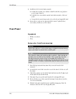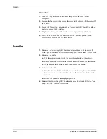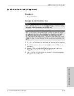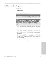
Right Heat Sink Component
8-22
Force EZ-C Series Service Manual
3.
Remove the Control board.
a.
Remove the screw that secures the retention bracket to the left rear heat
sink. Set the screw and bracket aside for reinstallation.
b.
Unlock the connector on the Control board and disconnect the Display
board ribbon cable from the Control board.
c.
Carefully slide the Control board straight up to disconnect it from the
Power Supply/RF board. Set the board aside in an antistatic container for
reinstallation.
4.
Disconnect the right heat sink resistor cable from J12 on the Power Supply/RF
board.
5.
Remove the two screws that secure the heat sink to the chassis. Next, insert
the screwdriver into the holes on the outside of the chassis and remove the two
screws that secure the heat sink to the Power Supply/RF board. Set the screws
aside for reinstallation.
6.
Carefully lift the right heat sink to disconnect the heat sink components from
their sockets on the Power Supply/RF board.
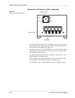
Replace the Right Heat Sink Components
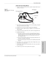
Figure 8-5.
Right heat sink components
•
To replace the damping resistor FET, remove the screw and washer that
secure the FET to the heat sink. Position the new damping resistor FET on the
heat sink and reinstall the washer and screw.
•
To replace the RF power diode, remove the screw that secures the diode to the
heat sink. Position the new RF power diode on the heat sink and reinstall the
screw.
Small circuit board
Damping resistor
RF power diode
Power MOSFET
Damping resistor FET

