Calibrating the Force EZ-C Series Electrosurgical Generator
Setup, T
e
st
s, and Adjustment
s
Force EZ-C Series Service Manual
6-29
Calibration Step 5 – Check and Adjust the Current Sense
Gain
Equipment
•
Two short test cables (less than 24 inches long) with banana plugs
•
Current transformer (such as the Pearson Model 411 or equivalent)
•
True RMS voltmeter (such as the Fluke 8920 or equivalent)
•
10 ohm noninductive power resistor (such as the Dale NH-250)
•
Bipolar footswitch and monopolar footswitch
Checking the Current Sense Gain for Bipolar Output
1.
Verify that the Bipolar display shows calibration step number 5.
The Cut and Coag displays show the I (current) factor. If it is four or more
digits, the most significant digits appear in the Cut display.
2.
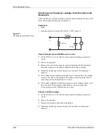
Connect the test equipment for bipolar output.
a.
Connect the two test cables to the Bipolar Instrument receptacle.
b.
Pass one test cable through the current transformer and connect the current
transformer to the voltmeter.
c.
Connect the 10 ohm resistor across the output jacks at the end of the test
cables.
d.
Connect the bipolar footswitch to the Bipolar Footswitch receptacle on the
rear panel.
or
Connect the monopolar footswitch to the Footswitch receptacle on the front
panel and press the Footswitch Selector button until the left arrow indicator
illuminates green.
Caution
To avoid inadvertent coupling and/or shunting of RF currents around the resistor
elements, keep the resistors at least 10.2 cm (4 in.) away from any metal surface
including tabletops and other resistors. This is especially true if several resistors
are connected in series or parallel to obtain a specified value. Do not allow the
resistor bodies to touch each other.
Notice
Do not activate the generator with any load resistor higher than 10 ohms while
calibrating the current sense gain. Otherwise, product damage will result.

