5-2
Force EZ-C Series Service Manual
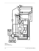
Figure 5-1.
A block diagram of the
Force EZ-C Series generator
RMS to DC
Con
ve
rter
V
oltage
Sense
Current
Sense
Current
Sense
Output
Resonator
RMS to DC
Con
ver
ter
RMS to DC
Con
ve
rter
RMS to DC
Con
ve
rter
A to D Con
ve
rt
er
A to D Con
ve
rt
er
Dual P
o
rt
RAM
SYS_ECON
Dosage Error
I2_SEN
V2_SEN
VPK+
HV_SEN
V
oltage
Scaling
Foots
witch
Decode
Ser
ial
Po
rt
Displa
y
K
e
yboard
A
udio
Main
Microcontroller
Foots
witch Command
Ser
ial Data
Displa
y Data
Control Input
A
udio
Control
Batter
y
B
a
cke
d
RAM
W
atchdog
Calibration V
alues
LV
DC Monitor
Digital P
encil Button Commands
Feedbac
k
Microcontroller
Output
Wa
ve
fo
rm
Microcontroller
Isolation
Circuit
P
encil Button Switch
Wires
Output
Amplifier
Digital to
Analog
Con
ve
rter
Output and
Scaling Rela
ys
V
a
riab
le Output
High V
oltage
DC
P
o
wer Supply
I_SEN
V_SEN
R_SEN
REM
Circuit
Output
Tr
ansf
or
mer
Rela
y
Control
HVDC Control
Wa
ve
fo
rm
Control
RF Dr
iv
e
T_ON A
V
G
Bipolar
Monopolar
Activ
e
P
atient
Cut/Coag
Buttons
Retur
n
Electrode
R_SEN
SYS_ECON
HV_SEN
T_ON A
V
G
Real-
Ti
m
e
Clock
Calibration V
alues
Date/T
ime


