Periodic Safety Check
Setup, T
e
st
s, and Adjustment
s
Force EZ-C Series Service Manual
6-21
5.
Verify under normal conditions (ground closed, normal polarity) the leakage
current is less than 20 microamps. If the leakage current is greater than 20
microamps, call the Valleylab Service Center.
6.
Verify under single fault conditions (ground open) the leakage current is less
than or equal to 100 microamps. If the leakage current is greater than
100 microamps, call the Valleylab Service Center.
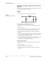
Output Receptacles and REM Sink Current
1.
Set the DVM to AC volts (200 mV) and connect the leakage current test
circuit.
2.
Turn on the generator at 140 Vac and connect the end of the leakage current
test circuit to 140 volts through a 120 k
Ω
resistor.
3.
Connect the other side of the IEC leakage load to each of the output
receptacles (including the Patient Return Electrode receptacle)
4.
Determine the leakage current using the conventional 1 microamp per 1
millivolt.
5.
Verify the leakage current is less than or equal to 20 microamps. If the leakage
current is greater than 20 microamps, call the Valleylab Service Center.
Checking High Frequency Leakage Current and Ground
Resistance
Check the high frequency leakage current and ground resistance before returning
the Force EZ-C Series Electrosurgical Generator to clinical use. Check the
leakage current at these times:
•
after calibrating the generator
•
every six months
Equipment
•
200 ohm, 250 watt, noninductive resistor
•
Current transformer
•
True RMS voltmeter (Fluke 8920 or equivalent)
•
Bipolar and monopolar footswitches and handswitching accessories
•
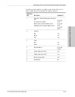
Leakage table—per IEC 60601-2-2 1991, Figure 104
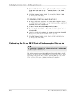
Checking Monopolar High Frequency Leakage Current
1.
Connect the 200 ohm load from the active accessory through the current
transformer to the equipotential ground lug on the rear of the generator.
2.
Connect the current transformer to a true RMS voltmeter.
3.
Connect a monopolar footswitch to the Monopolar Footswitch receptacle at
the rear of the generator.


