Calibrating the Force EZ-C Series Electrosurgical Generator
Setup, T
e
st
s, and Adjustment
s
Force EZ-C Series Service Manual
6-33
3.
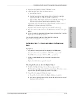
Replace the 3000 ohm load with the 2000 ohm resistor.
4.
Check and adjust the V factor for the blend mode.
a.
Press the Blend button.
b.
Press the footswitch cut pedal and check the voltmeter for a reading
equivalent to 0.300 +0/–.006 A
rms
(0.294 to 0.300 A
rms
).
c.
Stop activation. If the output current was not within the stated range, use
the Cut and Coag Power Control knobs to adjust the V factor.
Approach the value from the low side. Adjust until the current is as close as
possible to 0.300 A
rms
, but not over 0.300 A
rms
.
Repeat 4b and 4c until the output current is within the stated range.
5.
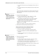
Disconnect the test cables and remove the 2000 ohm resistor from monopolar
output.
6.
To save the voltage sense gain calibration and go to calibration step 7, turn the
Bipolar Power Control knob clockwise.
Next, check the reactance gain factor as described in
Calibration
Step 7 – Check and adjust the reactance gain
.
Calibration Step 7 – Check and Adjust the Reactance
Gain
Equipment
•
Two short test cables (less than 24 inches long) with banana plugs
•
Current transformer (such as the Pearson Model 411 or equivalent)
•
True RMS voltmeter (such as the Fluke 8920 or equivalent)
•
50 and 200 ohm noninductive power resistors (such as the Dale
NH-250)
•
Bipolar footswitch and monopolar footswitch
Checking the Reactance Gain for Bipolar Output
1.
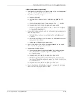
Verify that the Bipolar display shows calibration step number 7.
The Cut and Coag displays show the Z (reactance) factor. If it is four or more
digits, the most significant digits appear in the Cut display.
2.
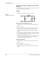
Connect the test equipment for bipolar output.
a.
Connect the two test cables to the Bipolar Instrument receptacle.
b.
Pass one test cable through the current transformer and connect the current
transformer to the voltmeter.

