background image

Responding to System Alarms

T

roubleshooting

Force EZ-C Series Service Manual

7-11

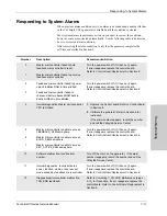
Responding to System Alarms

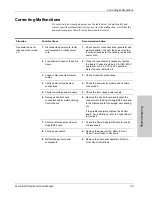
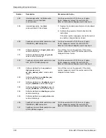
When a system alarm condition exists, an alarm tone sounds and a number flashes 
in the Cut display. The generator is disabled until the condition is cleared.

Most system alarms require some action on your part to correct the condition; 
however, some are corrected automatically. Use the following table to determine 
how to correct an alarm condition.

After correcting the alarm condition, verify that the generator completes the 
self-test as described in Section 5.

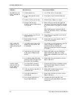
Number

Description

Recommended Action

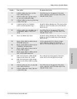
0

1

Master microcontroller failed to hold 
feedback microcontroller in reset.

Master microcontroller failed to power up 
feedback microcontroller

Turn the power switch off (O) then on (I) again.
If error reappears, replace the control board.
Refer to 

Control Board Replacement

 in Section 8.

2

3

Feedback microcontroller failed to power 
up and initialize RAM in time allotted.

Feedback microcontroller failed to 
checksum battery-backed RAM data in 
dual-port RAM in time allotted.

Turn the power switch off (O) then on (I) again.
If error reappears, replace the control board.
Refer to 

Control Board Replacement

 in Section 8.

4

Internal diagnostics. Master microcontroller 
CPU test failed.

1.

Replace the Control board. Refer to 

Control Board 

in Section 8.

2.

Calibrate the generator. Refer to Section 6 for 
instruction.

If the alarm number appears, record the number 
and call the Valleylab Service Center.

5

6

7

Master microcontroller unable to access 
FEEDBACK_SEM semaphore.

Master microcontroller unable to access 
ECON_SEM semaphore.

Master microcontroller unable to access 
KEY_ACTIVE_SEM semaphore.

Turn the power switch off (O) then on (I) again.
If error reappears, replace the control board.
Refer to 

Control Board Replacement

 in Section 8.

10

Software malfunction. Invalid alarm 
number.

Turn off, then turn on the generator.  If the alarm 
number reappears, record the number and call the 
Valleylab Service Center.

11

Internal diagnostics. Invalid activated 
power, function, mode, or key request 
mode echoed by feedback microcontroller.

Turn the power switch off (O) then on (I) again.
If error reappears, replace the control board.
Refer to 

Control Board Replacement

 in Section 8.

12

Diagnostics/microcontroller malfunction. 
TON_ERR test failed.

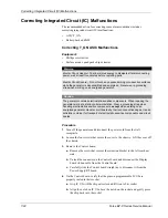
Refer to 

Correcting T_ON ASIC Malfunctions

 (steps 

4–11) in this section. If error reappears, replace the 
control board. Refer to 

Control Board Replacement

 in 

Section 8.

Summary of Contents for Force EZ - C Series

Page 1: ...Service Manual Valleylab Force EZ C Series Electrosurgical Generator with Instant Response Technology...

Page 2: ...onse Technology consists of two parts the text part 1 of 2 and a Schematics Supplement part 2 of 2 which contains the schematics Valleylab Part Number 1015435 part 1 of 2 Effective Date November 2008...

Page 3: ...ip or maintenance suggestion Warning Indicates a potentially hazardous situation which if not avoided could result in death or serious injury Caution Indicates a hazardous situation which if not avoid...

Page 4: ...art of Valleylab Valleylab neither assumes nor authorizes any other person to assume for it any other liability in connection with the sale or use of any of Valleylab s products Notwithstanding any ot...

Page 5: ...resolving disputes arising under or relating in any way to this warranty is the District Court of the County of Boulder State of Colorado USA Valleylab its dealers and representatives reserve the righ...

Page 6: ...vi Force EZ C Series Service Manual...

Page 7: ...2 2 Instant Response Technology 2 3 Bipolar Modes 2 3 Monopolar Cut and Coag Modes 2 3 Cut Modes 2 3 Coag Modes 2 4 REM Contact Quality Monitoring System 2 4 How the REM System Works 2 5 Electrodes Wi...

Page 8: ...Transients Emergency Generator Mains Transfer 4 9 Output Characteristics 4 14 Available Power Settings in Watts 4 14 Maximum Output for Force EZ C Series Electrosurgical Generator Modes 4 15 Output Wa...

Page 9: ...o Circuit 5 26 Footswitch Decode Circuit 5 28 Temperature Sense Circuit 5 28 Section 6 Setup Tests and Adjustments Setting Up the Generator 6 2 Connections for Bipolar Surgery 6 4 Setting the Bipolar...

Page 10: ...Check and Adjust the Reactance Gain 6 33 Calibration Step 8 Check and Adjust the ECON Factor 6 35 Section 7 Troubleshooting Inspecting the Generator 7 2 Correcting Malfunctions 7 3 Responding to Syste...

Page 11: ...Remove the Left Rear Heat Sink 8 19 Replace the Left Rear Heat Sink Components 8 20 Install the Left Rear Heat Sink 8 21 Right Heat Sink Component 8 21 Equipment 8 21 Remove the Right Heat Sink 8 21 R...

Page 12: ...rvice Centers 9 4 Section 10 Service Parts Ordering Replacement Parts 10 2 Force EZ C Series Electrosurgical Generator Assembly 10 3 Generator Assembly Parts List 10 5 Control Board Components 10 7 Fo...

Page 13: ...ohms generator setting vs output power 4 25 Figure 4 16 Low 1 Desiccate mode peak voltage vs output power 4 25 Figure 4 17 Low 2 Desiccate mode 300 ohms generator setting vs output power 4 26 Figure 4...

Page 14: ...re 8 5 Right heat sink components 8 22 Figure 8 6 Connections to the low voltage power supply 8 25 Figure 8 7 Cable connections to the power entry module 8 27 Figure 10 1 Exploded view of Force EZ C S...

Page 15: ...Safety Valleylab stresses safety in the use and servicing of its electrosurgical equipment This section presents the following Safety information Warnings Cautions and Notices Refer to the Preface Con...

Page 16: ...only one instrument at a time Do not attempt to connect more than one instrument at a time into a given receptacle Doing so will cause simultaneous activation of the instruments Caution Do not stack...

Page 17: ...t activate the Valleylab REM Contact Quality Monitoring System Warning Danger Explosion Hazard Do not install the generator in the presence of flammable anesthetics gases liquids or objects Fire Hazar...

Page 18: ...DC circuitry and associated mounting and heat sink hardware described in this manual They are not isolated from the AC line Take appropriate precautions when testing and troubleshooting this area of...

Page 19: ...with any load resistor lower than 3000 ohms while calibrating the voltage sense gain for the pure cut mode Otherwise product damage will result Do not activate the generator with any load resistor low...

Page 20: ...1 6 Force EZ C Service Manual...

Page 21: ...r servicing the Valleylab Force EZ C Series Electrosurgical Generator This section introduces the features and components of the generator Additional information about using the generator is available...

Page 22: ...stem compatibility List of Components The Valleylab Force EZ C Series Electrosurgical Generator is a self contained unit It consists of a main enclosure cover and base and power cord It includes the f...

Page 23: ...low 1 high 1 and high 2 coag settings Bipolar Modes The Force EZ C Series Electrosurgical Generator provides a standard bipolar mode usable for most bipolar applications Delicate tissue requires less...

Page 24: ...al sparking to adjacent areas can occur as tissue at the surgical site dries and becomes more resistant to current flow For details about the monopolar output characteristics refer to Section 4 Techni...

Page 25: ...ot have the REM safety feature the REM system does not monitor the patient contact area as previously described The REM system monitors only the pin to pin resistance at the connector and can detect b...

Page 26: ...de feature is available only when the most recently used modes and power settings feature is turned off You can select either low desiccate or high fulgurate as the default coag mode for the Force EZ...

Page 27: ...SECTION 3 Force EZ C Series Service Manual 3 1 3Controls Indicators and Receptacles This section describes the front and rear panels including all controls indicators and receptacles...

Page 28: ...the knob clockwise To decrease the power turn the knob counterclockwise D Cut Indicator When you activate the generator in cut mode this bar illuminates yellow and an activation tone sounds E Cut Dis...

Page 29: ...the active electrode M High Fulgurate Button Select to fulgurate an area of tissue with a spray of sparks N REM Alarm Indicator This indicator illuminates red until you properly apply a REM patient r...

Page 30: ...ou can connect either a handswitching instrument three pin connector or a footswitching instrument single pin connector to this receptacle To activate a footswitching instrument connect a monopolar fo...

Page 31: ...connected to the Bipolar Instrument receptacle When the right arrow indicator illuminates green the footswitch activates the instrument connected to the Accessory Instrument receptacle The footswitch...

Page 32: ...ivate the generator When any alarm occurs You can adjust the volume of the activation tones However to ensure that the surgical team is alerted to inadvertent activation you cannot turn the activation...

Page 33: ...about this panel G Bipolar Footswitch Receptacle Connect a single pedal bipolar footswitch to this receptacle if you connect an instrument to the Bipolar Instrument receptacle on the front panel The f...

Page 34: ...Specifications Figure 3 4 The option panel on the generator rear panel with the plate removed to show the serial and RF activation ports Serial Port Allows connection of a computer to the generator Y...

Page 35: ...anual 4 1 1Technical Specifications All specifications are nominal and subject to change without notice A specification referred to as typical is within 20 of a stated value at room temperature 77 F 2...

Page 36: ...in each Mounting Valleylab Universal Cart UC8009 Force Argon Unit or any stable flat surface Width 40 6 cm 16 in Depth 39 5 cm 15 6 in Height 12 7 cm 5 in Weight 6 8 kg 15 lbs Ambient temperature rang...

Page 37: ...nerator and change the power settings while this condition exists Internal Memory Ambient temperature range 34 to 65 C 29 to 149 F Relative humidity 25 to 85 noncondensing Atmospheric pressure 500 to...

Page 38: ...hen RF output is not activated REM patient return electrode 5 to 135 ohms or up to a 40 increase in the initial measured contact resistance whichever is less Patient return electrode without the REM s...

Page 39: ...eds 20 ohms the REM Alarm indicator flashes red a tone sounds twice and the generator disables RF output The indicator remains illuminated red until you correct the condition causing the alarm Then th...

Page 40: ...Cable H05VVF3G1 0 VDE maximum length 15 5 meters Plug minimum 6 A 250VAC Unit receptacle IEC female minimum 6 A 250VAC 100 120 Volt 220 240 Volt Maximum VA input Idle 50 VA Bipolar 500 VA Cut 850 VA...

Page 41: ...Frequency RF Leakage Current Enclosure source current ground open 100 A Source current patient leads all outputs Normal polarity intact ground 10 A Normal polarity ground open 50 A Reverse polarity g...

Page 42: ...ground DANGER Explosion risk if used with flammable anesthetics Rear Panel To reduce the risk of electric shock do not remove the cover Refer servicing to qualified service personnel Front Panel Dang...

Page 43: ...compatibility Voltage Transients Emergency Generator Mains Transfer The Force EZ C Series Electrosurgical Generator operates in a safe manner when you transfer between line AC and an emergency genera...

Page 44: ...nvironment guidance RF emissions CISPR 11 Group 1 The Force EZ C Series Electrosurgical Generator uses RF energy only for its internal function Therefore its RF emissions are very low and are not like...

Page 45: ...l environment Surge IEC 61000 4 5 1 kV differential mode 2 kV common mode 1 kV differential mode 2 kV common mode Mains power quality should be that of a typical commercial or hospital environment Vol...

Page 46: ...eld strengths from fixed RF transmitters as determined by an electromagnetic site survey should be less than the compliance level in each frequency range Interference may occur in the vicinity of equi...

Page 47: ...he maximum output power of the communications equipment Rated maximum output power of transmitter W Separation distance according to frequency of transmitter m 150 kHz to 80MHz d 0 5 P 80MHz to 800MHz...

Page 48: ...34 35 36 37 38 39 40 45 50 55 60 65 70 1 2 3 4 5 6 7 8 9 10 11 12 13 14 15 16 17 18 19 20 21 22 23 24 25 26 27 28 29 30 31 32 33 34 35 36 37 38 39 40 45 50 55 60 65 70 75 80 85 90 95 100 110 120 130 1...

Page 49: ...2 23 24 25 26 27 28 29 30 31 32 33 34 35 36 37 38 39 40 45 50 55 60 65 70 75 80 85 90 95 100 110 120 Mode Open Circuit P P Voltage max Rated Load max Power max Crest Factora typical Rated Load Bipolar...

Page 50: ...nerator controls maximum output voltage to reduce capacitive coupling and video interference and to minimize sparking Bipolar Monopolar Cut Monopolar Coag Standard 470 kHz sinusoid Pure 393 kHz sinuso...

Page 51: ...for each mode at specific power settings Bipolar Graph The insulating surface described in IEC 60601 2 2 and full length leads was used to obtain the bipolar output measurements Figure 4 1 Standard Bi...

Page 52: ...ut output measurements Figure 4 2 Pure mode load resistance vs output power Figure 4 3 Blend mode load resistance vs output power 0 200 400 600 800 1000 1200 1400 1600 1800 2000 350 300 250 200 150 10...

Page 53: ...ll length leads were used to obtain the monopolar coag output measurements Figure 4 4 Low 1 Desiccate mode load resistance vs output power Figure 4 5 Low 2 Desiccate mode load resistance vs output pow...

Page 54: ...ower Figure 4 7 High 1 Fulgurate mode load resistance vs output power 0 200 400 600 800 1000 1200 1400 1600 1800 2000 140 120 100 80 60 40 20 0 120 W 60 W Load Resistance ohms Output Power watts 0 200...

Page 55: ...Output Power vs Resistance Graphs Technical Specifications Force EZ C Series Service Manual 4 21 Figure 4 8 High 2 Fulgurate mode load resistance vs output power Load Resistance Output Power watts...

Page 56: ...4 9 Standard Bipolar mode 100 ohms generator setting vs output power Figure 4 10 Standard Bipolar mode peak voltage vs output power 0 10 20 30 40 50 60 70 0 20 40 60 70 50 30 10 Generator Setting Outp...

Page 57: ...ure mode 300 ohms generator setting vs output power Figure 4 12 Pure mode peak voltage vs output power 0 50 100 150 200 250 300 0 100 200 300 Output Power watts Generator Setting 0 200 400 600 800 100...

Page 58: ...generator setting vs output power Figure 4 14 Blend mode peak voltage vs output power 0 20 40 60 80 100 120 140 160 180 0 50 100 150 200 200 Generator Setting Output Power watts 0 200 400 600 800 1000...

Page 59: ...5 Figure 4 15 Low 1 Desiccate mode 500 ohms generator setting vs output power Figure 4 16 Low 1 Desiccate mode peak voltage vs output power Output Power watts Generator Setting 0 500 1000 1500 2000 25...

Page 60: ...300 ohms generator setting vs output power Figure 4 18 Low 2 Desiccate mode peak voltage vs output power 0 20 40 60 80 100 0 20 100 120 120 40 60 80 Generator Setting Output Power watts 0 50 100 150...

Page 61: ...mode 300 ohms generator setting vs output power Figure 4 20 Low 3 Desiccate mode peak voltage vs output power Output Power watts 0 20 40 60 80 100 0 20 100 120 120 40 60 80 Generator Setting 0 50 100...

Page 62: ...ohms generator setting vs output power Figure 4 22 High 1 Fulgurate mode peak voltage vs output power Generator Setting Output Power watts 0 20 40 60 80 100 0 20 100 120 120 40 60 80 0 500 1000 1500 2...

Page 63: ...de 500 ohms generator setting vs output power Figure 4 24 High 2 Fulgurate mode peak voltage vs output power 0 20 40 60 80 100 0 20 100 120 120 40 60 80 Output Power watts Generator Setting 0 500 1000...

Page 64: ...4 30 Force EZ C Series Service Manual...

Page 65: ...C Series Electrosurgical Generator circuitry resides on four printed circuit boards the Control board the Display board the Footswitch board and the power supply radio frequency RF board This section...

Page 66: ...itch Command Serial Data Display Data Control Input Audio Control Battery Backed RAM Watchdog Calibration Values LVDC Monitor Digital Pencil Button Commands Feedback Microcontroller Output Waveform Mi...

Page 67: ...ize sparking It applies this technology to all generator modes except the low 1 desiccate coag setting and the two high fulgurate coag settings For details refer to Instant Response Algorithm in this...

Page 68: ...the generator extinguishes the indicator light If the generator detects a break in continuity between the electrode and the generator the REM alarm indicator illuminates red When resistance between th...

Page 69: ...grated circuit or ASIC It generates the RF drive waveforms T_ON for the RF output stage Main Microcontroller The main microcontroller U5 is an 80C562 that incorporates an 8 input multiplexed 8 bit ana...

Page 70: ...arameters Feedback Microcontroller The feedback microcontroller U11 is an 80C562 It receives commands from the main microcontroller and when the generator is activated establishes the appropriate rela...

Page 71: ...each and 1 port of 4 bits Of the general I O pins 24 can by alternatively utilized for 24 PLD outputs The PSD835G2 also contains 512K x 8 main flash memory 32K x 8 boot flash memory 2K x 8 of SRAM an...

Page 72: ...ies for the feedback microcontroller to output 0 to 5 Vdc analog voltages Waveform Generation T_ON ASIC A dedicated 89C54 microcontroller U9 generates the RF waveforms T_ON for the RF output amplifier...

Page 73: ...unts which guarantees the T_ON waveform generator is still operating It still does not allow The T_ON average to drop below the lower limit of 15 counts mentioned above Audio Alarm The audio alarm cir...

Page 74: ...nt calculated by the backup sensors should not deviate from the current calculated by the primary sensors by more than 50 of the value calculated by the primary sensors In power control mode the power...

Page 75: ...t current protects output circuitry At high impedances constant voltage control limits arcing and electromagnetic interference EMI Constant Current The algorithm holds output current constant accordin...

Page 76: ...for changing power settings REM switch circuit footswitch decoding circuit for the front panel Footswitch receptacle Bipolar Cut and Coag Power Setting Encoders Three mechanical encoders S1 S3 and S6...

Page 77: ...these digital signals reducing high frequency emissions The lowered impedance also reduces the susceptibility of the circuit to noise from other circuits LED and Seven Segment Display Drivers This cir...

Page 78: ...n bipolar output or single pin accessory output S4 and S5 select the pure and blend cut modes S7 and S8 select the low or high coag modes FETs Q2 Q3 and Q6 select a bank of switches for the main micro...

Page 79: ...associated circuitry The footswitch connector P1 provides the connecting point for the footswitch The common mode choke L1 and capacitors C1 C3 C16 C18 and C24 C26 provide filtering that blocks high...

Page 80: ...or on the footswitch cables The audio circuit on the Power Supply RF board uses the speaker SP1 on the Footswitch board to enunciate the presence of RF output and to provide an auditory indication of...

Page 81: ...ge Power Supply The high voltage power supply contains several circuits the power entry circuitry auto mains switching circuitry AC DC conversion circuitry a DC DC switching regulator Power Entry Circ...

Page 82: ...AC DC Converter The AC DC converter uses CR80 as either a doubler or full wave rectifier depending on the input voltage In either case it provides an unregulated nominal 300 Vdc to the DC DC switchin...

Page 83: ...N is compared to the feedback voltage from the output divider R21 and R22 and an error signal ECON is sent to the PWM microcontroller In addition to the error signal U4A and the associated R C network...

Page 84: ...has internal current limiting overvoltage and thermal shutdown protection The low voltage power supply connects to the Power Supply RF board through four pins The significant specifications of the lo...

Page 85: ...es with the primary of T12 work in concert with the 100 ohm resistor across the secondary to divide the output voltage down to a manageable level Depending on the front panel power setting one of thre...

Page 86: ...o the redundant voltage sensing circuit follows for rectification division limiting buffering and filtering The signals produced from the redundant sense circuits are scaled for zero to 5 Vdc operatio...

Page 87: ...quency of 27 1 kHz For a given power setting blend gives a higher peak current providing better hemostasis than pure To minimize ringing at the beginning of the off period of the blend waveform envelo...

Page 88: ...heavy to light loads the output voltage rises faster than the microcontroller can respond This analog circuit works outside the microcontroller loop at a much greater speed The rectified but unfilter...

Page 89: ...rmer T10 and capacitors C149 C151 and C157 form a resonant circuit with a nominal operating frequency of 80 kHz This frequency is positioned between RF output harmonics to prevent electrosurgical RF n...

Page 90: ...tive to Coag switch closure in a handswitching accessory accomplishes handswitch activation Current limiting resistors in series with LEDs in the optoisolators cause the LEDs to light to a controlled...

Page 91: ...n simultaneously Under normal operating conditions the ALARM signal is low allowing the U5C output to float while the U5D output transistor is turned on The output of U5D creates a voltage divider thr...

Page 92: ...s circuit using the ISO_TST signal The main microcontroller asserts ISO_TST to shut down U11 and discharge V_ISO_4 Using comparators U7A U7B and U9A to gate Vref2 allows loopback testing of the footsw...

Page 93: ...Adjustments After unpacking or after servicing the Valleylab Force EZ C Series Electrosurgical Generator set it up and verify that it functions correctly If the generator does not satisfactorily compl...

Page 94: ...d by your institution connect an equipotential grounding cable to the grounding lug on the rear panel of the generator Then connect the cable to earth ground 4 Plug the generator power cord into the r...

Page 95: ...urate setting momentarily appear in the Coag display 7 If the self test is successful a tone sounds Verify the following Either the Pure button indicator or the Blend button indicator illuminates gree...

Page 96: ...t panel Warning Electric Shock Hazard Do not connect wet accessories to the generator Ensure that all accessories and adapters are correctly connected and that no metal is exposed Caution Accessories...

Page 97: ...se a footswitch to activate a handswitching instrument For most procedures you will connect only one monopolar instrument handswitching or footswitching Caution Set power levels to the lowest setting...

Page 98: ...nections handswitching instrument Figure 6 5 Monopolar connections footswitch activation from the Monopolar Footswitch receptacle on the rear panel handswitching instrument patient return electrode ha...

Page 99: ...High button While you press the Low button a 1 low 1 2 low 2 or 3 low 3 appears in the Coag display While you press the High button a 1 high 1 or 2 high 2 appears in the Coag display To change these s...

Page 100: ...wo patient return electrodes do not touch Setting Up the Special Features Five special features are available to customize the Force EZ C Series Electrosurgical Generator Refer to the following table...

Page 101: ...shes Recall of most recently used modes and power settings 1 Press the Pure button 2 Turn the Cut Power Control knob to turn on or turn off this feature 0 off 1 on 0 or 1 Pure flashes blank Default co...

Page 102: ...w mode For example if you set the power to 250 for pure cut when you select the blend mode the setting changes to 200 the maximum for blend If however you set the power to 65 in the low desiccate coag...

Page 103: ...activates the return electrode circuit to eliminate the possibility of current dispersal Notice Do not activate the generator until the forceps have made contact with the patient Product damage may oc...

Page 104: ...Confirm outputs Check leakage current and ground resistance Recommended Test Equipment Digital voltmeter Fluke 77 or 87 or equivalent True RMS voltmeter Fluke 8920 or equivalent Oscilloscope Tektronix...

Page 105: ...nt Panel 1 Check the Footswitch receptacle for obstructions or damage Check for a secure fit by inserting the monopolar footswitch connector into the receptacle If the connection is loose replace the...

Page 106: ...llation 3 Verify that all connectors are firmly seated 4 Inspect each board for damaged components wires cracks and corrosion If you find evidence of damage on the Control board Display board or Foots...

Page 107: ...tings feature momentarily appears in the Cut display The selected low and high settings momentarily appear in the Coag display Tones sound to verify that the speaker is working properly 2 If the self...

Page 108: ...s green 6 Decrease the resistance to 10 ohms and verify that the REM Alarm indicator illuminates green 7 Decrease the resistance to 3 ohms and verify that the REM alarm sounds 8 Switch to a connector...

Page 109: ...rear panel 3 Set the bipolar power to 70 4 Test the output current for the bipolar mode a Press the footswitch pedal and while activating the generator note the output on the voltmeter b Release the...

Page 110: ...propriate mode button refer to the table below 4 Set the cut power refer to the table below 5 Test the monopolar cut output a Press the footswitch cut pedal and while activating the generator note the...

Page 111: ...the range specified in the table below 5 Repeat steps 1 through 4 for each coag mode setting and resistor combination For information on changing the low and high settings refer to Setting Up the Spe...

Page 112: ...le and earth ground Record the largest reading 4 Determine the leakage current using the conventional 1 microamp per 1 millivolt 5 Verify under normal conditions ground closed normal polarity the leak...

Page 113: ...rrent using the conventional 1 microamp per 1 millivolt 5 Verify the leakage current is less than or equal to 20 microamps If the leakage current is greater than 20 microamps call the Valleylab Servic...

Page 114: ...RMS voltmeter 3 Connect a bipolar footswitch to the Bipolar Footswitch receptacle at the rear of the generator 4 Activate the footswitch in each mode at maximum control setting Record the leakage curr...

Page 115: ...ication Calibration Step Description Adjustable 1 Force EZ C Series Electrosurgical Generator data Generator model number Master microcontroller software version Feedback microcontroller software vers...

Page 116: ...ode When you are in calibration mode the calibration step number appears in the Bipolar display The value s associated with each calibration step appear in the Cut and Coag displays Use the Cut and Co...

Page 117: ...olar Power Control knob at the end of the step The values that were in effect before you started that step remain in effect Calibration Step 1 Verify the Force EZ C Series Electrosurgical Generator Da...

Page 118: ...r Control knob on the front panel to adjust these values To increase the displayed value turn the Coag Power Control knob clockwise To decrease the value turn the Coag Power Control knob counterclockw...

Page 119: ...calibration step number 3 2 To select the hour turn the Coag Power Control knob until the correct value 0 23 appears in the Coag display Examples For 2 AM set the hour value to 2 For 2 PM set the val...

Page 120: ...he resistor substitution box to the Patient Return Electrode receptacle on the front panel 3 Verify that the Coag display shows 135 4 Set the resistor substitution box to 135 ohms a Turn the Coag Powe...

Page 121: ...the Bipolar Instrument receptacle b Pass one test cable through the current transformer and connect the current transformer to the voltmeter c Connect the 10 ohm resistor across the output jacks at t...

Page 122: ...st cables through the current transformer c Connect a monopolar footswitch to the Monopolar Footswitch receptacle on the rear panel 2 Check and adjust the I factor for the pure mode a Press the Pure b...

Page 123: ...in Calibration Step 6 Check and adjust the voltage sense gain Calibration Step 6 Check and Adjust the Voltage Sense Gain Equipment Two short test cables less than 24 inches long with banana plugs Cur...

Page 124: ...Disconnect the test cables and remove the resistors Checking the Voltage Sense Gain for Monopolar Output 1 Connect the test equipment for monopolar output a Connect the test cables to the Monopolar In...

Page 125: ...libration and go to calibration step 7 turn the Bipolar Power Control knob clockwise Next check the reactance gain factor as described in Calibration Step 7 Check and adjust the reactance gain Calibra...

Page 126: ...l the current is as close as possible to 1 100 Arms but not over 1 100 Arms Repeat 3a and 3b until the output current is within the stated range 4 Disconnect the test cables and remove the 50 ohm resi...

Page 127: ...5 To save the reactance gain calibration and go to calibration step 8 turn the Bipolar Power Control knob clockwise Next go to Calibration Step 8 Check and adjust the ECON factor Calibration Step 8 C...

Page 128: ...nt receptacle b Connect the 100 ohm resistor to the test cables c Connect a monopolar footswitch to the Monopolar Footswitch receptacle on the rear panel 2 Check the pure output a Press the Pure butto...

Page 129: ...t a Verify that the test cables are connected to the Monopolar Instrument receptacle b Pass one test cable through the current transformer and connect the current transformer to the voltmeter c Connec...

Page 130: ...utton Verify that the high mode is indicated the Cut display shows 1 and the Coag display shows 10 watts 9 Adjust the ECON factor for high 1 a Press the coag pedal and while activating the generator u...

Page 131: ...shooting If the generator is not functioning properly use the information in this section to perform the following tasks Identify and correct the malfunction If a system alarm number was displayed tak...

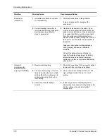
Page 132: ...hat all accessory cords are properly connected Check the power cord Replace the power cord if you find exposed wires cracks frayed insulation or a damaged connector Open the fuse drawer and inspect th...

Page 133: ...20 240 V operation or 8 0 A 110 120 V operation Refer to Fuses in Section 8 3 Loose or disconnected internal cables 3 Check all internal connections 4 Faulty power entry module or connections 4 Check...

Page 134: ...Turn off then turn on the generator to clear the number Calibrate the generator For instructions refer to Calibrating the Force EZ C Series Electrosurgical Generator in Section 5 2 Faulty battery on C...

Page 135: ...panel is not functioning correctly 1 Front panel footswitch provides output only to Accessory Instrument receptacle and you want output to the Monopolar Instrument receptacle 1 Connect the footswitch...

Page 136: ...put 2 Faulty connection from Footswitch board to Power Supply RF board 2 Check the ribbon cable and its connections 3 Malfunctioning or damaged rear panel footswitch receptacle 3 Replace the Footswitc...

Page 137: ...itch receptacle is being used for instrument connected to Monopolar Instrument receptacle 4 Connect the footswitch to the rear panel Monopolar Footswitch receptacle or If you are using a footswitching...

Page 138: ...m further detailed component troubleshooting as needed 11 RF output stage malfunction high voltage is present during activation 11 If high voltage is present during activation at TP20 on the Power Sup...

Page 139: ...ices only when generator is activated 1 Metal to metal sparking 1 Check all connections to the generator patient return electrode and accessories 2 High settings used for fulguration 2 Use lower power...

Page 140: ...ients with pacemakers during surgery and keep a defibrillator available Consult the pacemaker manufacturer or hospital Cardiology Department for further information when use of electrosurgical applian...

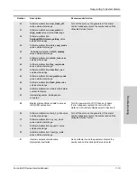
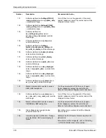
Page 141: ...pears replace the control board Refer to Control Board Replacement in Section 8 4 Internal diagnostics Master microcontroller CPU test failed 1 Replace the Control board Refer to Control Board in Sect...

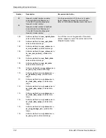
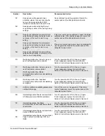
Page 142: ...ction 17 18 19 Isns and or Vsns voltage detected without activation REM circuit failure REM oscillator frequency outside acceptable operating range Overvoltage detected on 5V power supply Do not attem...

Page 143: ...nable to find alarm number to display Internal diagnostics Settings data corrupted Turn off then turn on the generator If the alarm number reappears record the number and call the Valleylab Service Ce...

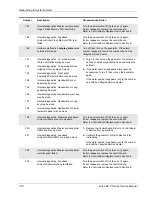
Page 144: ...in re_non_rem_control outside state range Software malfunction rem_flash_state value outside state range Software malfunction rem_led_state value outside state range Software malfunction coag_state v...

Page 145: ...ling calibration step If the alarm number reappears record the number and call the Valleylab Service Center 123 124 125 126 Master microcontroller unable to access GEN_SEM semaphore Master microcontro...

Page 146: ...state range Turn off then turn on the generator If the alarm number reappears record the number and call the Valleylab Service Center 151 Master microcontroller unable to access GEN_SEM semaphore Tur...

Page 147: ...n 8 171 172 Watchdog malfunction Correct value not sent from master microcontroller Watchdog malfunction Master microcontroller unable to access watchdog semaphore Turn the power switch off O then on...

Page 148: ...witch or bipolar footswitch pedal may be stuck 1 Turn off then turn on the generator Do not press buttons or accessory activation devices during the self test 2 If the alarm number reappears disconnec...

Page 149: ...tics Firmware not compatible with hardware Turn the power switch off O then on I again If error reappears replace the control board Refer to Control Board Replacement in Section 8 214 REM circuit malf...

Page 150: ...r reappears record the number and call the Valleylab Service Center 232 Feedback microcontroller unable to access KEY_ACTIVE_SEM semaphore Turn the power switch off O then on I again If error reappear...

Page 151: ...on master microcontroller Software malfunction Delay time out of bounds on feedback controller Software malfunction data_type in me_rtc_get outside of range Software malfunction data_type in me_rtc_p...

Page 152: ...it from the Power Supply RF board 4 On the Control board verify that the pins on programmable IC U9 are properly seated in their socket a Grip IC U9 with the chip extractor and lift it out of its sock...

Page 153: ...1 7 If the alarm number reappears replace programmable IC U9 a Turn off the generator b Remove the Control board step 3 c Grip IC U9 with the chip extractor and lift it out of its socket d Align the n...

Page 154: ...button cell battery so that the positive side of the battery is facing out visible Refer to Control board Components in Section 9 for the Valleylab replacement battery or call the Valleylab Service C...

Page 155: ...secures the bracket to the heat sink c Connect the Display board ribbon cable to the Control board and lock the connector 6 Calibrate the generator Refer to Section 6 for instructions If the calibrati...

Page 156: ...7 26 Force EZ C Series Service Manual...

Page 157: ...knobs power switch and REM lever assembly Fuses including two in the fuse drawer one on the low voltage power supply and one on the Power Supply RF board Handle Heat sink left front left rear and righ...

Page 158: ...Interconnect Diagram 8 2 Force EZ C Series Service Manual Interconnect Diagram Figure 8 1 Electric cable connections...

Page 159: ...he positive side of the battery faces out visible b Snap the battery into the socket so it is firmly seated 6 Position the cover above the chassis and slide it down Tighten the four screws that secure...

Page 160: ...ght heat sink Slide the board down carefully fitting the edge connector into the matching connector on the Power Supply RF board 8 Place the retention bracket on the left rear heat sink and install th...

Page 161: ...the screws for reinstallation d Slide the front panel assembly forward carefully disengaging it from the electrical contacts on the Power Supply RF board Warning Electric Shock Hazard To allow stored...

Page 162: ...e lever and the board 2 Attach the Display board to the front panel a Position the Display board inside the front panel and connect the Footswitch receptacle cable to the connector on the Display boar...

Page 163: ...Board earlier in this section Footswitch Board Assembly Equipment Phillips screwdriver 1 Turn off the generator and disconnect the power cord from the wall receptacle 2 Loosen the four screws that se...

Page 164: ...connector on the Control board and disconnect the Display board ribbon cable from the Control board 4 Disconnect the power switch cable from the Power Supply RF board 5 Remove the four screws that sec...

Page 165: ...lever and spring from the Display board 2 Remove the Footswitch receptacle and install it on the new front panel a Note the location of the ground wire Then remove the four screws that secure the Foot...

Page 166: ...Control board and lock the connector 5 Position the cover above the chassis and slide it down Tighten the four screws that secure the cover to the chassis Front Panel Footswitch Receptacle Do not rem...

Page 167: ...he front panel and install the new clip that secures the knob to the front panel 5 Reinstall the front panel assembly Refer to Front Panel earlier in this section Warning Electric Shock Hazard To allo...

Page 168: ...connected cable out the opening Figure 8 2 Power switch and cable connections 1 Check and correct the cable connections on the new power switch assembly using the illustration and the assembly you ju...

Page 169: ...board 5 Install the Display board a Position the Display board inside the front panel and connect the footswitch receptacle cable to the connector on the Display board b Place the Display board over...

Page 170: ...he Control board a Remove the screw that secures the retention bracket to the left rear heat sink Set the screw and bracket aside for reinstallation b Unlock the connector on the Control board and dis...

Page 171: ...s that secure the cover to the chassis Replacing the Fuse on the Power Supply RF Board Equipment Phillips screwdriver Fuse puller Warning Fire Hazard For continued protection against fire hazard repla...

Page 172: ...ndle 1 Remove the Power Supply RF board and attached heat sinks observe all warnings and cautions Refer to Power Supply RF board later in this section 2 Remove the handle a Tilt the generator onto its...

Page 173: ...reinstallation 4 Carefully lift the left front heat sink to disconnect the heat sink components from their sockets on the board Warning Electric Shock Hazard To allow stored energy to dissipate after...

Page 174: ...Position the new diode on the heat sink and reinstall the washer and screw Install the Left Front Heat Sink 1 Slide the left front heat sink component leads into the matching sockets on the Power Sup...

Page 175: ...ert the screwdriver into the holes on the outside of the chassis and remove the two screws that secure the heat sink to the Power Supply RF board Set the screws aside for reinstallation 6 Carefully li...

Page 176: ...e or more of the four HVPS FETs remove the screw and washer that secure the FET to the heat sink Position the new FET on the heat sink and reinstall the washer and screw To replace the bridge rectifie...

Page 177: ...ent Phillips screwdriver Remove the Right Heat Sink 1 Turn off the generator and disconnect the power cord from the wall receptacle 2 Loosen the four screws that secure the cover to the chassis Lift t...

Page 178: ...chassis Next insert the screwdriver into the holes on the outside of the chassis and remove the two screws that secure the heat sink to the Power Supply RF board Set the screws aside for reinstallati...

Page 179: ...ower Supply RF board 2 Through the holes on the outside of the chassis install the two screws that secure the heat sink to the Power Supply RF board 3 Install the two screws that secure the heat sink...

Page 180: ...aside in an antistatic container for reinstallation 4 Remove the two screws that secure the low voltage power supply to the rear panel Save them for reinstallation 5 Snap the low voltage power supply...

Page 181: ...offs on the rear panel and press to snap it in place 5 Install the two screws that secure it to the rear panel 6 Install the Control board a Fit the edge of the Control board into the slot on the righ...

Page 182: ...nnect the power entry module cable from the Power Supply RF board 6 Remove the two screws that secure the power entry module to the rear panel Save the screws for reinstallation 7 Slide the module out...

Page 183: ...5 Install the Control board a Position the Control board over the Power Supply RF board fitting the edge of the board into the slot on the right heat sink Slide the board down carefully fitting the ed...

Page 184: ...embly forward carefully disengaging it from the electrical contacts on the Power Supply RF board 4 Remove the Control board a Remove the screw that secures the retention bracket to the left rear heat...

Page 185: ...RF Board and Heat Sinks 1 Slide the Power Supply RF board and attached heat sinks into the chassis until it drops into place Slide it slightly toward the back of the chassis to lock it in place Verify...

Page 186: ...lectrical contacts on the Power Supply RF board b Install the four screws that secure the front panel to the chassis c Connect the power switch cable to J14 on the Power Supply RF board d Connect the...

Page 187: ...Series Service Manual 9 1 1Repair Policy and Procedures Refer to this section for the following information The manufacturer s responsibility Returning the generator for service Returning circuit boa...

Page 188: ...he generator call your Valleylab Representative for assistance If instructed to send the generator to Valleylab first obtain a Return Authorization Number Then clean the generator and ship it to Valle...

Page 189: ...ital phone number etc listed in Step 1 Obtain a Return Authorization Number B Be sure the generator is completely dry before you pack it for shipment Pack it in its original shipping container if avai...

Page 190: ...ters 9 4 Force EZ C Series Service Manual Service Centers For a complete list of service centers worldwide please refer to the Valleylab website http www valleylab com valleylab international service...

Page 191: ...SECTION 10 Force EZ C Series Service Manual 10 1 2Service Parts In this section Ordering replacement parts Replacement parts lists...

Page 192: ...able Replace all components with parts of identical construction and value Replacement part ratings and tolerances must be equal to or better than original Substituting lower grade parts can adversely...

Page 193: ...Electrosurgical Generator Assembly Force EZ C Series Service Manual 10 3 Service Parts Force EZ C Series Electrosurgical Generator Assembly Figure 10 1 Exploded view of Force EZ C Series Electrosurgic...

Page 194: ...Force EZ C Series Electrosurgical Generator Assembly 10 4 Force EZ C Series Service Manual Figure 10 2 Top view of Force EZ C Series Electrosurgical Generator parts after assembly...

Page 195: ...ink assemblies See Power Supply RF Board Components in this section 201 340 009 4 Assembly right heat sink Includes Heat sink large Transistor FET Transistor FET HI V N CH Diode ultra fast 30 A 1000 V...

Page 196: ...embly low voltage power supply input 207 500 531 10 Cable assembly power 4 wire 207 500 532 11 Assembly Footswitch board Refer to Footswitch Board Components in this section 201 342 002 12 Assembly po...

Page 197: ...M4 x 6 mm 4 Screw panhd M3 x 10 mm 6 Screw panhd M4 x 10 mm 4 Fuse LVPS F2A Serial number label Serial tag Tag receptacle notice Ground symbol label 207 002 061 207 002 060 213 150 121 223 301 159 223...

Page 198: ...103 R2 56 2 1 1 8 W 234 201 169 R3 1 43 k 1 1 8 W 234 201 304 Miscellaneous Item 2 Speaker 8 241 003 001 Item 3 Screw metric M3 x 8 mm lg 4 237 050 149 Item 4 Nut hex M3 x 0 5 stl zinc pld 4 224 300 0...

Page 199: ...C141 C142 C146 C148 C153 0 1 F 20 50 V 204 200 460 C2 C12 C26 C78 C79 C111 C122 C127 C130 C140 C155 C160 C164 C168 C169 1 F 20 50 V 204 200 464 C3 C51 C63 C68 C90 22 F 20 25 V 204 600 063 C8 C10 C22 1...

Page 200: ...V 204 300 130 C66 C91 680 pF 5 500 V 204 105 022 C119 470 pF 5 500 V 204 105 018 C67 1 F 10 250 V 204 400 153 C70 2 F 10 400 V 1000630 C85 C99 047 20 50 V 204 200 517 C89 C108 15 F 10 200 V 204 400 15...

Page 201: ...CR12 CR15 CR26 CR32 CR37 1N5233B 239 600 000 CR18 CR21 CR29 CR35 CR38 CR40 Zener 1N5240B 10 V 239 600 001 Fuses F1 Fuse 5 x 20 mm F6 3A 215 100 041 F1 Fuse holder 215 100 526 Relays K1 Socket relay 20...

Page 202: ...1 1 8 W 234 201 485 R6 R97 R99 R103 R107 R109 R110 R114 R116 2 k 1 1 8 W 234 201 318 R8 1 6 k 5 1 4 W 234 024 068 R9 R12 110 k 5 1 4 W 234 024 112 R11 510 5 1 4 W 234 024 056 R13 R125 Thermistor 1 k...

Page 203: ...R170 R171 R173 10 k 1 1 8 W 234 201 385 R32 R33 R74 R165 R167 R172 2 15 k 1 1 8 W 234 201 321 R34 R35 R75 R166 R168 R169 1 4 k 1 1 8 W 234 201 303 R36 R38 R50 R90 2 k 5 1 4 W 234 024 070 R40 R58 R63...

Page 204: ...W 234 014 122 R94 39 k 5 1 2 W 234 014 113 R95 47 5 1 4 W 234 024 031 R100 750 5 1 4 W 234 024 060 R105 R106 R112 R113 499 1 1 8 W 234 201 260 R118 270 k 5 1 4 W 234 024 121 R120 68 k 5 1 4 W 234 024...

Page 205: ...uare core REM 251 300 045 T12 Voltage sense 251 300 044 Integrated Circuits U1 U12 U29 MOSFET driver TSC1427 210 800 012 U2 U7 U9 U14 U35 U36 LM 393 N 210 300 011 U3 PWM controller high speed 210 720...

Page 206: ...50 094 Miscellaneous Item 2 Assembly right heat sink 202 750 101 Item 3 Assembly left front heat sink 202 750 102 Item 4 Assembly left rear heat sink 202 750 100 Item 5 Sleeving PVC clear 15 awg 249 0...

Page 207: ...pins 208 300 871 J10 Connector 96 pin 208 300 721 J11 Connector phone jack 208 400 113 J13 Connector PC edge 208 157 031 J14 Connector PCB 8 ckt 208 160 058 J15 J16 Contact monopolar 223 500 085 J17 J...

Page 208: ...10 18 Force EZ C Series Service Manual...

Reviews: