132
RL5000 S
ERIES
XS
CALE
AND
X2 A
UTOMATED
T
ELLER
M
ACHINES
S
ERVICE
M
ANUAL
Section 3
6. Open the security cabinet door by en ter ing the cor rect com bi na tion and re-
leasing the lock mech a nism.
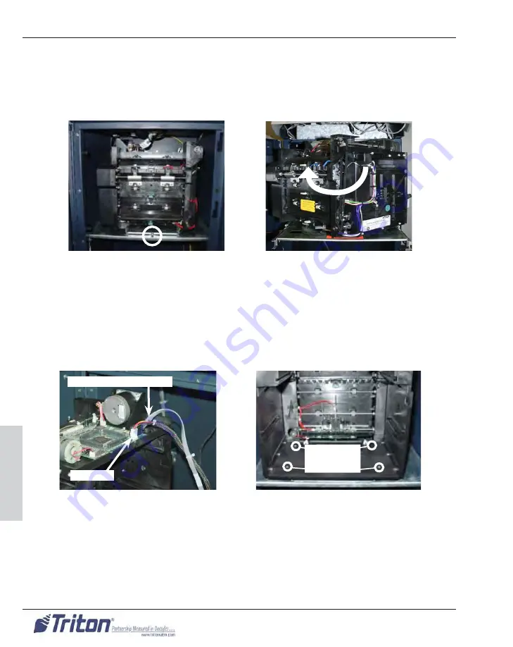
7. Refer to Figures 3-124 and 3-125. Pull down on the turntable locking pin
down and ro tate the turn ta ble clock wise 180 degrees to the service position.
8. Re
move the note cassette from the dispensing mechanism.
9. Re
move the reject cassette from the dispensing mechanism.
10. Refer to Figure 3-126. Unplug the RJ45 serial communications cable from
J11 and the DC power cable at J1 on the dispensing mech a nism control PCB.
11. Refer to Fig ure 3-127. Use a Phillips screw driv er with a #2 tip to remove
the four (4) mounting screws that se cure the dis pens er mech a nism to the
turn ta ble.
12. Remove the TDM-100 dis pens ing mech a nism from the turntable/tray assem-
bly.
Figure 3-126. Connections on the
TDM control PCB.
DC Power
Serial Communications
Figure 3-127. The TDM-100 in the "ser-
vice position (cassettes removed).
Mounting
Screws
Figure 3-124. Location of the turn-
table locking pin on TDM-100
mounting tray
Figure 3-125. Rotating the TDM-
100 clockwise to the service po-
sition
Summary of Contents for RL5000
Page 2: ...ii RL5000 SERIES XSCALE AND X2 AUTOMATED TELLER MACHINES SERVICE MANUAL...
Page 14: ...xiv RL5000 SERIES XSCALE AND X2 AUTOMATED TELLER MACHINES SERVICE MANUAL Preface...
Page 19: ...2 RL5000 SERIES XSCALE AND X2 AUTOMATED TELLER MACHINES SERVICE MANUAL Section 1...
Page 21: ...4 RL5000 SERIES XSCALE AND X2 AUTOMATED TELLER MACHINES SERVICE MANUAL Section 1...
Page 29: ...12 RL5000 SERIES XSCALE AND X2 AUTOMATED TELLER MACHINES SERVICE MANUAL Section 2...
Page 51: ...34 RL5000 SERIES XSCALE AND X2 AUTOMATED TELLER MACHINES SERVICE MANUAL Section 3...
Page 162: ...145 INDEX Index INDEX...


