background image

E6581381

E-8

5

EOQF

 : Command mode selection

HOQF

 : Frequency setting mode selection 1

Function
Remote mode selection, these parameters are used to specify which input device (operation panel,
terminal board, serial communication) takes priority in entering an operation stop command or a frequency
setting command, VIA, VIB, operation panel, serial communication device, external contact up/down).
At Local mode selection, the start/stop operation and frequency setting by operation panel is prior with no
relation of 

EOQF

/

HOQF

setting.

<Command mode selection>

Title

Function

Adjustment range

Default setting

EOQF

Command mode selection

0: Terminal board
1: Operation panel
2: Serial communication

0

Programmed value

:

Terminal board
operation

ON and OFF of an external signal Runs and stops operation.

:

Operation panel
operation

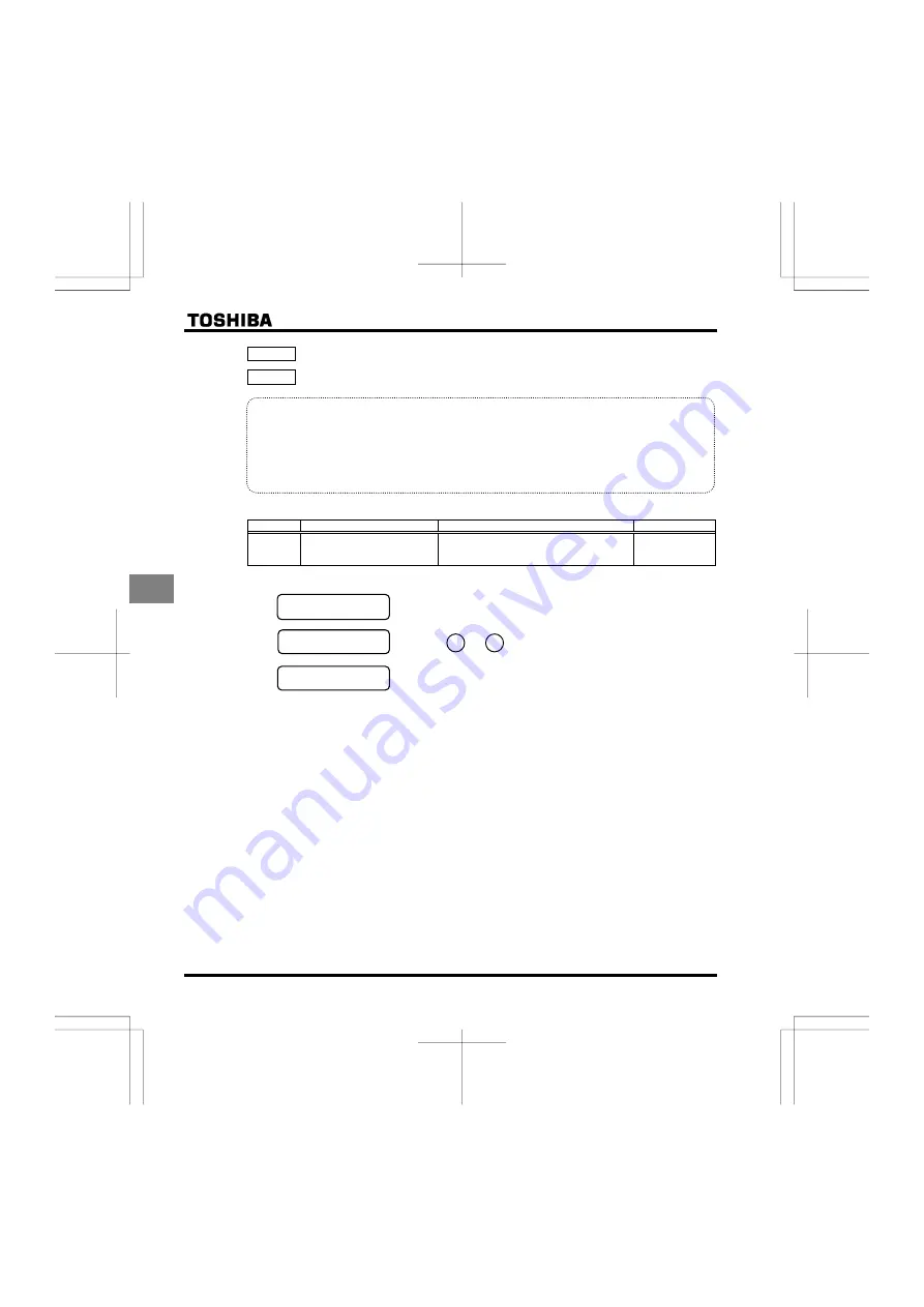
Press the         and         keys on the operation panel to start and stop.

Serial communication
operation

Run and stop through serial communication.

* There are two types of function: the function that conforms to commands selected by 

EOQF

, and the function

that conforms only to commands from the terminal board.

 See the table of input terminal function selection in Chapter 11.

* When priority is given to commands from a linked computer or terminal board, they have priority over the

setting of 

EOQF

.

STOP

RUN

Summary of Contents for TOSVERT VF-FS1 Series

Page 1: ...Y OVERSEAS SALES MARKETING DEPT ELECTRICAL APPARATUS MEASUREMENT DIV 1 1 Shibaura 1 chome Minato Ku Tokyo 105 8001 Japan TEL 81 0 3 3457 4911 FAX 81 0 3 5444 9268 TOSHIBA I NTERNATIONAL CORPORATION 13131 West Little York RD Houston TX 77041 U S A TEL 1 713 466 0277 FAX 1 713 896 5226 TOSHIBA ASIA P ACIFIC PTE LT D 152 Beach Rd 16 00 Gateway East Singapore 189721 TEL 65 6297 0900 FAX 65 6297 5510 T...

Page 2: ......

Page 3: ...ll be described in or near the symbol in either text or picture form Indicates danger What is dangerous will be described in or near the symbol in either text or picture form Indicates warning What the warning should be applied to will be described in or near the symbol in either text or picture form Limits in purpose This inverter is used for controlling speeds of three phase induction motors in ...

Page 4: ...e inverter This can result in electric shock or fire 2 1 2 2 2 Mandatory Turn power on only after attaching the front cover or closing door if enclosed in a cabinet If power is turned on without the front cover attached or closing door if enclosed in a cabinet this can result in electric shock or other injury If the inverter begins to emit smoke or an unusual odor or unusual sounds immediately tur...

Page 5: ...annot be stopped immediately by the inverter alone thus risking an accident or injury All options used must be those specified by Toshiba The use of any other option may result in an accident 1 4 4 1 4 4 1 4 4 1 4 4 1 4 4 Warning See item Prohibited When transporting or carrying do not hold by the front panel covers The covers may come off and the unit will drop out resulting in injury Do not inst...

Page 6: ... 1 2 1 2 1 1 4 4 Be Grounded Ground must be connected securely If the ground is not securely connected it could lead to electric shock or fire when a malfunction or current leak occurs 2 1 2 2 Warning See item Prohibited Do not attach equipment such as noise filters or surge absorbers that have built in capacitors to the output motor side terminals That could result in a fire 2 1 Operations Danger...

Page 7: ...will restart them suddenly after the specified time has elapsed This could result in unexpected injury Attach warnings about sudden restart in retry function on inverters motors and equipment for prevention of accidents in advance 6 12 3 6 12 3 Maintenance and inspection Danger See item Prohibited Do not replace parts This could be a cause of electric shock fire and bodily injury To replace parts ...

Page 8: ...ts in relation to inverters motors and other equipment Be sure to affix the caution label where it is easily visible when selecting the auto restart function See section 6 12 1 or the retry function See section 6 12 3 If the inverter has been programmed for restart sequence of momentary power failure place warning labels in a place where they can be easily seen and read Example of warning label If...

Page 9: ...rior basic performance 1 Automatic energy saving 2 Smooth operation Reduced rotation ripple through the use of Toshiba s unique waveform formation 3 Built in current surge suppression circuit Can be safely connected even if power load is low 4 Maximum 200Hz high frequency output Optimum for use with high speed motors such as those in lumber machinery and milling machines 5 Maximum carrier frequenc...

Page 10: ...meters D 3 5 Basic parameters E 1 5 1 Setting acceleration deceleration time E 1 5 2 Specifying an operation mode using parameters E 4 5 3 Selection of operation mode E 7 5 4 Meter setting and adjustment E 10 5 5 Standard default setting E 13 5 6 Forward reverse run selection Operation panel operation E 15 5 7 Maximum frequency E 16 5 8 Upper limit and lower limit frequencies E 16 5 9 Base frequen...

Page 11: ...rameters F 69 6 20 Operation panel parameter F 70 6 21 Communication function Common serial F 78 6 22 Parameters for options F 83 6 23 Permanent magnetic motors F 83 7 Applied operation G 1 7 1 Setting the operation frequency G 1 7 2 Setting the operation mode G 5 8 Monitoring the operation status H 1 8 1 Status monitor mode H 1 8 2 Display of trip information H 5 9 Measures to satisfy the standar...

Page 12: ...nings and remedies M 1 13 2 Restoring the inverter from a trip M 5 13 3 If the motor does not run while no trip message is displayed M 6 13 4 How to determine the causes of other problems M 7 14 Inspection and maintenance N 1 14 1 Regular inspection N 1 14 2 Periodical inspection N 2 14 3 Making a call for servicing N 5 14 4 Keeping the inverter in storage N 5 15 Warranty O 1 16 Disposal of the in...

Page 13: ...o those specifications not only will the three phase induction motor not rotate correctly it may also cause serious accidents through overheating and fire Related output current Power supply Related input current Inverter Type Inverter rated output capacity Warning label Power supply Motor capacity Series name Rating label Inverter main unit Carton box Name plate Warning label VF FS1 3PH 200 240V ...

Page 14: ...t in basic filter L Built in EMI class A filter D Built in EMI class B filter Operation panel P Provided Default interface logic WN Negative WP Positive Special specification code A is the number Input AC voltage 2 200V to 240V 4 380V to 480V Additional functions II None Standard product E Enclosed type This code represents the factory default logic setting You can switch from one input output log...

Page 15: ...E6581381 A 3 1 1 3 Names and functions 1 3 1 Outside view Operation panel ...

Page 16: ...ont panel locking screw The inverter came with this screw in the locked position So from this position turn the screw 90 counterclockwise to unlock the front panel or turn it 90 clockwise to lock the front panel The screw does not turn 360 To avoid damage to the screw do not use excessive force when turning it Unlock position mark Lock position mark Top warning label Note Colling fin Communicatio ...

Page 17: ... insulated tube or use the insulated lug connector 1 Power circuit terminal board In case of the lug connector cover the lug connector with insulated tube or use the insulated lug connector Screw size tightening torque M4 screw 1 3Nm 10 7lb y in M5 screw 2 5Nm 22 3lb y in M6 screw 4 5Nm 40 1lb y in M8 screw 12Nm 106lb y in M12 screw 41Nm 360lb y in ...

Page 18: ...E6581381 A 6 1 VFFS1 2004 2037PM VFFS1 4004 4055PL Note EMC plate is supplied as standard ...

Page 19: ...E6581381 A 7 1 VFFS1 2055 2075PM 4075 4110PL VFFS1 2110 2185PM 4150 4185PL Note EMC plate is supplied as standard ...

Page 20: ...cture shown in the figure below Connect a cable to part A if it has a ring terminal or to part B if it has no terminal bare wire Parts A and B accommodate different sizes of cables so consult the cable size list for the size of cable connectable to each part Note EMC plate is supplied as standard ...

Page 21: ...disconnecting the capacitor from the grounding line causes the inverter to become non compliant with the EMC directive Also note that the inverter must always be turned off before the capacitor is disconnected or reconnected Note In case of three phase 400V 5 5kW or less model if you disconnect the capacitor from ground set the parameter of carrier frequency H to 6kHz with motor cable length 30m o...

Page 22: ... Wire size Factory default settings of slide switches Solid wire 0 3 1 5 mm2 SW4 SINK Negative side WN type SOURCE Positive side WP type Stranded wire 0 3 1 5 mm2 FM SW2 V side AWG 22 16 VIA SW3 V side Sheath strip length 6 mm Screwdriver Small sized flat blade screwdriver Blade thickness 0 4 mm or less blade width 2 5 mm or less See section 2 3 2 for details on all terminal functions ...

Page 23: ...gn the dot on the screw with the unlock position mark upper side To avoid damage to the screw do not apply excessive force to turn the screw more than 90 degrees Pull the front panel toward you and swing it open to the left Terminal board cover Remove the terminal board cover by pulling it up toward you Remove the wiring port cover by pulling it down pass cables through the wiring port and connect...

Page 24: ... main circuit terminal board for models 22kW or more remomve the front cover Remove the screw Maincircuit terminal board Control circuit terminal board Open the control circuit terminal board cover To open the cover lift it with your finger placed at the part on the right side of the cover ...

Page 25: ...operate with the output decreased from rated load To carry out low speed operation continuously at the rated torque we recommend to use a inverter rated motor or a forced cooled motor designed for use with an inverter When operating in conjunction with a inverter rated motor you must change the inverter s motor overload protection level to VF motor use QNO Adjusting the overload protection level T...

Page 26: ...eration function or when vector control is selected adjust the speed control response stability factor or switch to V F control mode Combined with loads that have sharp fluctuations in rotation such as piston movements In this case please do not use this inverter Braking a motor when cutting off power supply A motor with its power cut off goes into free run and does not stop immediately To stop th...

Page 27: ...ation of their insulation depending on the cable length cable routing and types of cables used Here are some examples of measures against surge voltages 1 Lower the inverter s carrier frequency 2 Set the parameter H Carrier frequency control mode selection to or 3 Use a motor with high insulation strength 4 Insert an AC reactor or a surge voltage suppression filter between the inverter and the mot...

Page 28: ...breaking when two or more inverters are used on the same power line MCCB1 MCCBn 1 MCCB3 MCCB2 INV1 INV2 INVn circuit breaking fuse Breaking of selected inverter There is no fuse in the inverter s main circuit Thus as the diagram above shows when more than one inverter is used on the same power line you must select interrupting characteristics so that only the MCCB2 will trip and the MCCB1 will not...

Page 29: ... wires to other systems Leakage current will cause earth leakage breakers leakage current relays ground relays fire alarms and sensors to operate improperly and it will cause superimposed noise on the CRT screen or display of incorrect current detection with the CT Power supply ELCB Inverter Inverter M M ELCB Leakage current path across ground Remedies 1 If there is no radio frequency interference...

Page 30: ...having motors of low rated current several A ampere or less especially the 400V class low capacity 5 5kW or less models because the leak current will increase in proportion to the motor rating Remedies 1 Use the electronic thermal built into the inverter See section 5 12 The setting of the electronic thermal is done using parameter QNO VJT 2 Reduce the inverter s PWM carrier frequency However that...

Page 31: ...ilt into the inverter Use the monitor functions on the panel built into the inverter to check current values See section 8 1 1 1 4 4 Installation Installation environment The VF FS1 Inverter is an electronic control instrument Take full consideration to installing it in the proper operating environment Danger Prohibited Do not place any inflammable substances near the VF FS1 Inverter If an acciden...

Page 32: ... The inverter is a heat emitting body Make sure proper space and ventilation is provided when installing in the cabinet When installing inside a cabinet we recommend the top seal peeled off although 40 C or less Do not install in any location that is subject to large amounts of vibration Note If the VF FS1 Inverter is installed in a location that is subject to vibration anti vibration measures are...

Page 33: ...is necessary to hold motor shaft install a mechanical brake The brake on the inverter will not function as a mechanical hold and if used for that purpose injury may result Install the inverter in a well ventilated indoor place and mount it on a flat metal plate in portrait orientation If you are installing more than one inverter the separation between inverters should be at least 5 centimeters and...

Page 34: ... sealed storage cabinet m2 0 4 44 0 25 0 88 0 75 63 0 36 1 26 1 5 101 0 58 2 02 2 2 120 0 68 2 4 4 0 193 1 1 3 86 5 5 249 1 42 4 98 7 5 346 1 97 6 92 11 459 2 62 9 18 15 629 3 59 12 58 18 5 698 3 98 13 96 22 763 4 35 15 26 Three Phase 200V class 30 1085 6 18 21 7 0 4 45 0 26 0 9 0 75 55 0 31 1 1 1 5 78 0 44 1 56 2 2 103 0 59 2 06 4 0 176 1 0 3 52 5 5 215 1 23 4 3 7 5 291 1 66 5 82 11 430 2 45 8 6 ...

Page 35: ...de by side detach the caution label on the top surface of each inverter and use them where the ambient temperature will not rise above 40 C When using inverters where the ambient temperature will rise above 40 C leave a space of 5 cm or more between them and remove the caution label from the top of each inverter and operate each inverter at a current lower than the rated one Ensure a space of at l...

Page 36: ......

Page 37: ...ttaching the front cover or closing door if enclosed in a cabinet If power is turned on without the front cover attached or closing door if enclosed in a cabinet This can result in electric shock or other injury Electrical construction work must be done by a qualified expert Connection of input power by someone who does not have that expert knowledge may result in fire or electric shock Connect ou...

Page 38: ...nals is small use sleeved pressure terminals for the connections Connect the terminals so that adjacent terminals do not touch each other For ground terminal use wires of the size that is equivalent to or larger than those given in table 10 1 and always ground the inverter 200V voltage class D type ground 400V class C type ground Use as large and short a ground wire as possible and wire it as clos...

Page 39: ...E6581381 B 3 2 2 2 1 Standard connection diagram 1 This diagram shows a standard wiring of the main circuit ...

Page 40: ...E6581381 B 4 2 2 2 2 Standard connection diagram 2 ...

Page 41: ...of wiring of the main circuit Use options if necessary Power supply and motor connections Connections with peripheral equipment Motor Power supply Inverter Surge suppression filter No fuse braker R L1 S L2 T L3 V T2 U T1 W T3 IM Magnetic connector Input AC reactor noise reduction filter Zero phase reactor ...

Page 42: ... and specification of each terminal please refer to the following table See section 1 3 2 3 about the arrangement of control circuit terminals Control circuit terminals Terminal symbol Input output Function Electrical specifications Inverter internal circuits F Input Shorting across F CC causes forward rotation open causes slow down and stop When ST is always ON R Input Shorting across R CC causes...

Page 43: ... VIA 4 7 kΩ 1 2 W Also move the VIA SW3 dip switch to the V position 10Vdc internal impedance 30kΩ 4 20mA internalimpedance 250Ω VIB Input Multifunction programmable analog input Standard default setting 0 10Vdc 0 60Hz 0 50Hz frequency input PTC thermal input See section 6 17 15 10Vdc internal impedance 30kΩ FM Output Multifunction programmable analog output Standard default setting output frequen...

Page 44: ...cosφ 0 4 SINK Negative logic SOURCE Positive logic When the inverter s internal power supply is used Current flowing out turns control input terminals on These are called sink logic terminals The general used method in Europe is source logic in which current flowing into the input terminal turns it on Sink logic is sometimes referred to as negative logic and source logic is referred to as positive...

Page 45: ...als between analog input and contact input The functions of the VIA terminal can be selected between analog input and contact input by changing parameter settings H Factory default setting Analog input When using these terminals as contact input terminals in a sink logic circuit be sure to insert a resistor between the P24 and VIA terminals Recommended resistance 4 7KΩ 1 2W When using the VIA term...

Page 46: ... to the inverter and without supplying power If switching between sink source and PLC is done when power is turned on after switching or when the inverter is supplied with power the inverter might become damaged Confirm it before supplying power 2 Voltage current output switching Use the FM SW2 switch to switch between voltage output and current output Switch the FM terminal s voltage current outp...

Page 47: ... the inverter begins to emit smoke or an unusual odor or unusual sounds immediately turn power off If the equipment is continued in operation in such a state the result may be fire Call your local sales agency for repairs Always turn power off if the inverter is not used for long periods of time Turn input power on after attaching the front cover When enclosed inside a cabinet and using with the f...

Page 48: ...ting follow the selection of EOQF Command mode or HOQF Frequency setting mode 1 At default setting the switching between Local mode and Remote mode is effective When prohibiting this function refer to the chapter 6 20 1 2 At default setting when switched from remote of start or stop and running frequency at Remote mode are shifted to Local mode When changing from Local mode to Remote mode the inve...

Page 49: ... motor Motor starts Motor stops To switch between forward run and reverse run from the control panel the parameter HT forward reverse run selection needs to be set to or 2 RUN STOP by means of an external signal to the terminal board EOQF Sink Negative logic Use external signals to the inverter terminal board to start and stop the motor Short and terminals run forward Frequency ON OFF F CC Slow do...

Page 50: ...r HOQF and the parameter set value are displayed alternately Pressing the key twice returns the display to standard monitor mode displaying operation frequency 1 Setting the frequency using the operation panel HOQF Set the frequency with the operation panel Moves the frequency up Moves the frequency down Example of operating a run from the panel Key operated LED display Operation Displays the oper...

Page 51: ...signal Setting frequency using voltage signals 0 10V For more detailed information on adjustments see section6 5 Frequency 60Hz 0 0Vdc 10Vdc The input terminal VIB can be used in the same way HOQF VIA effective HOQF VIB effective For more details see section 6 5 Note Be sure to turn the VIA SW3 slide switch to the V voltage position CC VIA Voltage signal 0 10Vdc 3 Setting the frequency using curre...

Page 52: ...arameter setting Title Function Setting value EOQF Command mode selection 1 HOQF Frequency setting mode selection 1 3 3 Operation Run stop Press the and keys on the panel Frequency setting Set with the keys on the operation panel To store the set frequencies in memory press the key HEand the set frequency will flash on and off alternately Control circuit Motor IM R L1 S L2 T L3 U T1 V T2 W T3 PC P...

Page 53: ...xternal potentiometer VIA Input 4 20mAdc Use the VIA SW3 slide switch to switch between voltage and current to the VIA terminal Voltage input V side Current input I side Please turn off the lamp by pressing the key when the LOC REM key lamp is lit Control circuit Motor IM F R L1 S L2 T L3 U T1 V T2 W T3 Run forward signal R PC PA Power circuit Run backward signal MCCB CC Common CC VIB VIA PP Volta...

Page 54: ......

Page 55: ... display E When a current flows at or higher than the overcurrent stall level R When a voltage is generated at or higher than the over voltage stall level N When a load reaches 50 or higher of the overload trip value J When the temperature reaches the overheating protection alarm level Setting monitor mode The mode for setting inverter parameters How to set parameters See section 4 2 Status monito...

Page 56: ...E6581381 D 2 4 4 1 Flow of status monitor mode Flow of monitor as following ...

Page 57: ... by simply setting the parameters in one after another Parameter name CWH See section 4 2 4 This parameter has the function of displaying in reverse chronological order the five parameters that were changed last This function comes in very handy when you adjust the inverter repeatedly using the same parameter Parameter name CWJ See section 4 2 5 Adjustment range of parameters JK An attempt has bee...

Page 58: ... parameter setting Steps in key entry for basic parameters Example of setting procedure Changing the maximum frequency from 80Hz to 60Hz Key operated LED display Operation Displays the operation frequency operation stopped When standard monitor display selection H Operation frequency CWH The first basic parameter CWH Wizard function is displayed HJ Press either the or key to select HJ Pressing the...

Page 59: ... the reading of parameter setting MODE ENT Steps in key entry for extended parameters Switches to the setting monitor mode Displays CWH Selects H from basic parameters The first extended parameter HK Low speed signal output frequency is displayed Selects the extended parameter whose setting needs to be changed Reads the programmed parameter setting Changes the parameter setting Saves the changed v...

Page 60: ...lues If there is anything you do not understand during this operation press the MODE key several times to start over from the step of CWH display 4 2 3 Search and resetting of changed parameters I4W Automatically searches for only those parameters that are programmed with values different from the standard default setting and displays them in the user parameter group I4W Parameter setting can also...

Page 61: ...ey Press the MODE key once while the search is underway to return to the display of parameter setting mode After that you can press the MODE key to return to the status monitor mode or the standard monitor mode display of operation frequency If there is anything you do not understand during this operation press the key several times to start over from the step of CWH display 4 2 4 Setting a parame...

Page 62: ...setting of each parameter by pressing the or key and the ENT key GPF GPF is dialyzed on completion of the setting of the wizard parameter group Parameter display CWH HT H Press the MODE key to exit the wizard parameter group By pressing the MODE key you can return to the default monitoring mode display of operation frequency How Parameters of Quick setting wizard Title Function CW Automatic accele...

Page 63: ... first basic parameter CWH Wizard function is displayed CWJ Select the History function CWJ by pressing the or key CEE The parameter that was set or changed last is displayed Press the ENT key to display the set value Press the key and key to change set value CEE Press the ENT key to save the changed value The parameter name and the programmed value will flash on and off alternately Use the same s...

Page 64: ...H Base frequency 2 H Base frequency voltage 2 H H Protection parameters H Carrier frequency control mode selection H Auto tuning H H Motor constant parameters H H Motor control parameters H Stall prevention level 1 H Emergency stop selection H Output phase failure detection mode selection H Input phase failure detection mode selection H Detection of output short circuit during start up selection H...

Page 65: ...isplayed V R Press the key or the key to change to V R Pressing the ENT key displays the programmed parameters V R will always display zero on the right the previous setting on the left Press the key or the key to change the set value To return to standard factory default setting change to KPKV Pressing the ENT key displays KPKV while returning all parameters to factory default setting The monitor...

Page 66: ......

Page 67: ...atic acceleration deceleration This automatically adjusts acceleration and deceleration time in line with load size CW Adjusts the acceleration deceleration time automatically within the range of 1 8 to 8 times as long as the time set with the CEE or FGE depending on the current rating of the inverter CW Automatically adjusts speed during acceleration only During deceleration speed is not adjusted...

Page 68: ...oad that fluctuates considerably it may fail to adjust the acceleration or deceleration time in time and therefore may be tripped Methods of setting automatic acceleration deceleration Key operated LED display Operation Displays the operation frequency When standard monitor display selection H is set to Operation frequency CWH The first basic parameter CWH Wizard function is displayed CWK Press th...

Page 69: ...onds the inverter speed increases or reduces speed within 0 05 seconds If the programmed value is shorter than the optimum acceleration deceleration time determined by load conditions overcurrent stall or overvoltage stall function may make the acceleration deceleration time longer than the programmed time If an even shorter acceleration deceleration time is programmed there may be an overcurrent ...

Page 70: ...s always displayed on the right side The number on the left side refers to the number specified previously Example Automatically programmed functions and parameter set values Relational parameter Default setting value 1 Coast stop 2 3 wire operation 3 External input UP DOWN setting 4 4 20mA current input operation EO F 0 Terminal board 0 Terminal board 0 Terminal board 0 Terminal board 0 Terminal ...

Page 71: ...tion by simply pressing the ON OFF button Standard connection diagram Forward run Selecting HD operation holding with the input terminal selection parameter Select HD operation holding using the input terminal selection parameter and turn HD on to get the inverter ready for operation or turn HD off to stop operation Parameter setting When parameter CW is set to the following parameters are set aut...

Page 72: ...P DOWN cancellation from external contacts function to the VIA terminal separately See section 6 5 3 for details 4 20 mA current input CW Used for setting frequencies with 4 20mAdc current input R F HD Powered on Note 1 ON OFF ON OFF ON OFF ON OFF Output frequency Forward run Reverse run 0 Note 2 4 Operation frequency command Operation frequency command Note 4 When HD is OFF any attempt to turn on...

Page 73: ...de or HOQF Frequency setting mode Setting mode Switching of commands and references Key Commands EOQF Terminal board Operation panel Com priority cancellation Logic input CPCA 48 Run Forward Run Reverse References HOQF VIA Local Remote Logic input FCHG 38 Internal reference Serial communication H Operation panel Serial communication UP DOWN VIB Operation panel Serial communication UP DOWN VIB VIA ...

Page 74: ...tle Function Adjustment range Default setting EOQF Command mode selection 0 Terminal board 1 Operation panel 2 Serial communication 0 Programmed value Terminal board operation ON and OFF of an external signal Runs and stops operation Operation panel operation Press the and keys on the operation panel to start and stop Serial communication operation Run and stop through serial communication There a...

Page 75: ...requencies are set by commands from an external control unit UP DOWN frequency Terminals are used to specify an up down frequency command No matter what value the command mode selection EOQF and the frequency setting mode selection HOQF are set to the control input terminal functions described below are always in operative state Reset terminal default setting RES valid only for tripping Standby te...

Page 76: ...t current 1 5 times of rated current 2 Set frequency Maximum frequency HJ 3 DC voltage 1 5 times of rated voltage 4 Output voltage command value 1 5 times of rated voltage 5 Input power 1 85 times of rated power 6 Output power 1 85 times of rated power 7 Torque 2 5 times of rated torque 8 Torque current 2 5 times of rated torque 9 Motor cumulative load factor Rated load factor 10 Inverter cumulati...

Page 77: ...50Ω Note 2 Note that if HOUN is set to torque data will be updated at intervals of more than 40 ms Adjustment scale with parameter HO Meter adjustment Connect meters as shown below FM CC Meter Frequency meter default setting VF FS1 FM CC VF FS1 The reading of the frequency meter will fluctuate during scale adjustment Meter ammeter HOUN The reading of the ammeter will fluctuate during scale adjustm...

Page 78: ...r output current there are large fluctuations in data during adjustment making adjustment difficult the meter can be adjusted in inverter stop state When setting HOUN to for fixed output 1 100 output current a signal of absolute values will be output inverter s rated current 100 In this state adjust the meter with the HO Meter adjustment parameter Similarly if you set HOUN to for fixed output 2 ou...

Page 79: ...n time record clear 0 This function will be displayed as 0 during reading on the right This previous setting is displayed Example V R cannot be set during the inverter operating Always stop the inverter first and then program Programmed value 50Hz default setting V R Setting V R at causes all the following parameters to be set for operation using a base frequency of 50 Hz This does not change the ...

Page 80: ...V R to resets the cumulative operation time to the initial value zero Cumulative operation time clear V R Setting V Rto clears the trips when an GV R format error occurs But if the GV R displayed call us Save user setting parameters V R Setting V R to saves the current settings of all parameters See section 4 2 8 Load user setting parameters V R Setting V R to loads parameter settings to calls up ...

Page 81: ...rse to forward after displaying the message HT H Pressing the key again with the key held down changes the direction of rotation from forward to reverse after displaying the message HT T Check the direction of rotation on the status monitor For monitoring see section 8 1 HT H Forward run HT T Reverse run When the F and R terminals are used for switching between forward and reverse rotation from th...

Page 82: ...eased adjust the upper limit frequency WN as necessary Parameter setting Title Function Adjustment range Default setting HJ Maximum frequency 30 0 200 0 Hz 80 0 5 8 Upper limit and lower limit frequencies WN Upper limit frequency NN Lower limit frequency Function Programs the lower limit frequency that determines the lower limit of the output frequency and the upper limit frequency that determines...

Page 83: ...e frequency and the base frequency voltage in conformance with load specifications or the Base frequency Note This is an important parameter that determines the constant torque control area Output voltage V Base frequency voltage XNX XN Output frequency Hz 0 Title Function Adjustment range Default setting XN Base frequency 1 25 0 200 0 Hz 50 0 WP type 60 0 WN type XNX Base frequency voltage1 50 33...

Page 84: ... example the V F control mode selection parameter RV is set to Vector control Setting V F control mode selection to 3 sensorless vector control Key operated LED display Operation Displays the operation frequency Perform during operation stopped When standard monitor display selection H is set to Operation frequency CWH The first basic parameter CWH Wizard function is displayed RV Press the key to ...

Page 85: ...n RV to V F constant This is applied to load that requires the same torque at low speeds as at rated speeds Output voltage Base frequency voltage XNX Output frequency Hz XD Base frequency XN 0 To increase the torque further increase the setting value of the manual torque boost XD For more details see 5 11 2 Setting for fans and pumps Setting of V F control mode selection RV to variable torque This...

Page 86: ...y other case be sure to set the parameters H to H properly Be sure to set H rated current of motor and H rated speed of motor correctly as specified on the motor s nameplate For the setting of H no load current of motor refer to the motor test report There are two procedures for setting the other motor constants 1 The motor constant can be automatically set auto tuning Set the extended parameter H...

Page 87: ...r the setting of H no load current of motor refer to the motor test report There are two procedures for setting the other motor constants 1 The motor constant can be automatically set auto tuning Set the extended parameter H to For details see selection 1 in 6 15 1 2 Each motor constant can be set individually For details see selection 2 in 6 15 1 6 Operating a permanent magnet motor Setting of V ...

Page 88: ... in the vicinity of rated frequency to be somewhat lower 8 Connecting a reactor or surge voltage suppression filter between the inverter and the motor may reduce motor generated torque Setting auto tuning may also cause a trip GVP rendering sensorless vector control unusable 8 The following table shows the relationship between the V F control mode selection RV and the motor constant parameter Unde...

Page 89: ...ue 2 c H Auto tuning c c c H Slip frequency gain c H Automatic torque boost value H Motor rated current c c H Motor no load current c c c H Motor rated speed c c H Speed control response coefficient c c c H Speed control stability coefficient c c c H Exciting current coefficient c c H Stall prevention control coefficient 1 c c c c c H Stall prevention control coefficient 2 c c c c c H Motor adjust...

Page 90: ...is set to V F constant or square reduction Note The optimum value is programmed for each inverter capacity Be careful not to increase the torque boost rate too much because it could cause an overcurrent trip at startup 5 12 Setting the electronic thermal VJT Motor electronic thermal protection level 1 QNO Electronic thermal protection characteristic selection H Motor electronic thermal protection ...

Page 91: ...ad trip QN can be selected using the parameter QNO Explanation of terms Overload stall This is an optimum function for equipment such as fans pumps and blowers with variable torque characteristics that the load current decreases as the operating speed decreases When the inverter detects an overload this function automatically lowers the output frequency before the motor overload trip QN is activat...

Page 92: ...hen the VFFS1 2007PM is running with a 0 4kW motor having 2A rated current Key operated LED display Operation Displays the operation frequency Perform during operation stopped When standard monitor display selection H is set to Operation frequency CWH The first basic parameter CWH Wizard function is displayed VJT Press either the key or the key to change the parameter to VJT Press the ENT key to d...

Page 93: ...e inverter adjust the electronic thermal protection level 1 VJT so that it fits the motor s rated current If the indications are in percentages then 100 equals the inverter s rated output current A VJT 1 0 Output frequency Hz Output current reduction factor A 0 Setting the motor overload starting level 6Hz VJT 0 6 2 Motor 150 overload time limit H Parameter H is used to set the time elapsed before...

Page 94: ...ivated The calculated value of the electric thermal is memorized at power off The trip state can always be reset but the calculated value of the electric thermal can not be reset 5 13 Preset speed operation speeds in 7 steps UT UT Preset speed operation frequencies 1 7 Function A maximum of 7 speed steps can be selected just by switching an external contact signal Multi speed frequencies can be pr...

Page 95: ... SW4 set to sink logic O ON OFF Speed commands other than preset speed commands are valid when all are OFF Preset speed Terminal 1 2 3 4 5 6 7 R CC RES CC VIA CC Preset speed commands are not allocated to standard default setting Use the input terminal function selection to allocate SS1 to SS3 terminal Terminal R Input terminal function selection 2 R H Preset speed command 1 SS1 Terminal RES Input...

Page 96: ...on panel command valid Terminal command valid Operation panel command valid Communicatio n command valid Communic ation command valid Preset speed command Not entered Terminal command valid Operation panel command valid Communic ation command valid Note The preset speed command is always given priority when other speed commands are input at the same time Below is an example of 7 step speed operati...

Page 97: ... This signal can be used as an electromagnetic brake excitation release signal This signal can also be used as an operation signal when H is set to 0 0Hz because an ON signal is put out if the output frequency exceeds 0 0Hz Relay output 250Vac 1A cosφ 1 30Vdc 0 5A 250Vac 0 5A cosφ 0 4 at RY RC FLA FLC FLB terminals Parameter setting Title Function Adjustment range Default setting H Low speed signa...

Page 98: ...See page K 17 4 ON signal or 5 OFF signal 6 1 2 Output of designated frequency reach signal H Speed reach detection band Function When the output frequency becomes equal to the setting by designated frequency H an ON or OFF signal is generated Parameter setting Title Function Adjustment range Default setting H Speed reach detection band 0 0 HJ Hz 2 5 Parameter setting Title Function Adjustment ran...

Page 99: ...n the output frequency becomes equal to the frequency set by H H an ON or OFF signal is generated Parameter setting Title Function Adjustment range Default setting H Speed reach setting frequency 0 0 HJ Hz 0 0 H Speed reach detection band 0 0 HJ Hz 2 5 Parameter setting Title Function Adjustment range Setting value H Output terminal selection 1A RY RC 0 255 See page K 17 8 RCHF designated frequenc...

Page 100: ...Title Function Adjustment range Default setting H Analog contact input function selection VIA terminal 0 VIA analog input 1 VIA contact input Sink 2 VIA contact input Source 0 When using the VIA terminal as contact input terminals in sink logic connection be sure to insert a resistor between the P24 terminal and the VIA terminal Recommended resistance 4 7kΩ 1 2W Note When using the VIA terminal as...

Page 101: ...ctive function selection 2 0 71 See page K 15 1 Standby Coast stop The standard default setting is for deceleration stop To make a coast stop assign a 1 ST terminal function to an idle terminal using the programmable terminal function Change to H For coast stop OFF the ST terminal when stopping the motor in the state described at left The monitor on the inverter at this time will display QHH Motor...

Page 102: ...nput terminal function Terminal symbol Title Function Adjustment range Default setting H Always active function selection 1 0 H Always active function selection 2 1 ST F H Input terminal selection 1 F 2 F R H Input terminal selection 2 R 3 R RES H Input terminal selection 3 RES 0 71 See page K 15 10 RES VIA H Input terminal selection 8 VIA 0 71 Note 2 6 SS1 Note 1 The function that has been select...

Page 103: ...nals to the output no contacts switch of the programmable controller Use this function to specify forward reverse run or a preset speed operation Use a transistor that operates at 24Vdc 5mA CC Input terminal Inverter Programmable controller Interface between programmable controller and inverter Note When using a programmable controller with open collector outputs for control connect it to the PCL ...

Page 104: ...ction Use the above parameters to send various signals from the inverter to external equipment By setting parameters for the RY RC and FL FLA FLB and FLC terminals on the terminal board you can use 58 functions and functions obtained by combining them To assign only one function to RY RC terminals assign the function to H while leaving H and H as they are set by default Examples of application Fun...

Page 105: ...als set parameter H only Do not change but leave parameters H and H as they were set by default Default setting H 255 H 0 6 3 4 Assigning two functions to an output terminal H Output terminal selection 1A RY RC H Output terminal selection 1B RY RC H Output terminal logic selection RY RC Function 2 different functions can be assigned to the terminal board output terminal RY RC Signals of 2 function...

Page 106: ...al selection 1B 0 255 See page K 17 255 Always ON Two different functions can be assigned to terminals RY RC If parameter H is set to default a signal will be sent out when the two functions assigned are activated simultaneously Terminals RY RC Send out a signal when the functions assigned with H and H are activated simultaneously Timing chart ON OFF ON OFF ON OFF H H RY RC output Only one functio...

Page 107: ...ON OFF ON OFF H H RY RC output Only one function can be assigned to terminals FLA FLB FLC at a time 3 Holding the output of signals in ON status If the conditions for activating the functions assigned to output terminals RY RC agree with and as a result the output of signals is put in ON status the output of signals is held ON even if the conditions change Output terminal holding function Assign i...

Page 108: ...ment range Default setting H Frequency command agreement detection range 0 0 HJ Hz 2 5 HOQF Frequency setting mode selection 1 1 H Frequency setting mode selection 2 1 5 2 Note When using VIA terminal set H or H respectively to 52 or 53 to put out signals to RY RC or FLA FLB FLC When using VIB terminal set H or H respectively to 60 or 61 to put out signals to RY RC or FLA FLB FLC Note This functio...

Page 109: ... particular needs or operation mode Note The RV V F control mode selection parameter is enabled only for motor1 If motor 2 is selected V F control will be given constant torque characteristics Parameter setting Title Function Adjustment range Default setting H Base frequency 2 25 0 200 0 Hz 50 0 WP type 60 0 WN type H Base frequency voltage 2 50 330 V 200V class 50 660 V 400V class 230 WP WN type ...

Page 110: ...NX XD VJT CEE FGE HU H ON OFF OFF OFF CEE HU FGE H H HU OFF OFF OFF ON H H OFF ON OFF OFF RV XN H XNX H XD H VJT H ON RV XN H XNX H XD H VJT H H H CEE HU FGE H H HU Note The parameters XN XNX RV H and H cannot be switched during operation You need to stop operation when switching them 6 5 Frequency priority selection 6 5 1 Using a frequency command according to the particular situation HOQF Freque...

Page 111: ...OQF and H can be made by entering a command from a terminal board To do so however the frequency command forced switching function input terminal function selection 38 needs to be set beforehand to an input terminal board If an OFF command is entered to the input terminal board The command specified with HOQF will be selected If an ON command is entered to the input terminal board The command spec...

Page 112: ...equency H Communication command point 1 setting H Communication command point 1 frequency H Communication command point 2 setting H Communication command point 2 frequency Function These parameters adjust the output frequency according to the externally applied analog signal 0 10Vdc voltage 4 20mAdc current and the entered command for setting an external contact frequency To fine adjust the freque...

Page 113: ...ion command point 2 frequency 0 0 200 0 Hz 50 0 WP type 60 0 WN type Note Don t set the same value between point 1 and point 2 If set the same falue the GTT is displayed 1 0 10Vdc voltage input adjustment VIA VIB VIA VIB terminals The output frequency with respect to the voltage input is adjusted according to the selected reference point Gradient and bias can be set easily H H 100 10V voltage sign...

Page 114: ...l contact input DOWN frequency steps 0 0 FH Hz 0 1 H Initial up down frequency LL UL Hz 0 0 H Change of the initial up down frequency 0 Not changed 1 Setting of H changed when power is turned off 1 These functions take effect when parameter HOQF frequency setting mode selection 1 is set to or parameter H frequency setting mode selection 2 is set to is enabled Adjustment with continuous signals Par...

Page 115: ...er is turned on for the first time after the setting and therefore the output frequency will not rise until the operation frequency reaches the lower limit frequency Operation at the lower limit frequency In this case the time required for the operation frequency to reach the lower limit frequency can be shortened by setting HE to the lower limit frequency Adjustment with pulse signals Parameter s...

Page 116: ...down frequency About the change of the initial up down frequency To make the inverter automatically save the frequency immediately before it is turned off and start operation at that frequency next time power is turned on set H change of initial up down frequency to 1 which changes the setting of H when power is turned off Keep in mind that the setting of H is changed each time power is turned off...

Page 117: ...usted by default so that it will not produce an output until a certain amount of voltage is applied to the VIA and VIB input terminals If you want to reduce the leeway set H or H to a larger value Note that specifying a too large value may cause an output frequency to be output even though the operation frequency is 0 zero Hz Gain adjustment of VIA and VIB input terminals H and H The inverter is f...

Page 118: ...tting Title Function Adjustment range Default setting H Starting frequency setting 0 5 10 0 Hz 0 5 6 6 2 Run stop control with frequency setting signals H Operation starting frequency H Operation starting frequency hysteresis Function The Run stop of operation can be controlled simply with frequency setting signals Parameter setting Title Function Adjustment range Default setting H Operation start...

Page 119: ...ault setting H DC braking starting frequency 0 0 HJ Hz 0 0 H DC braking current 0 100 A 50 H DC braking time 0 0 20 0 sec 1 0 Time s DC braking starting frequency H DC braking current H DC braking time H Output frequency Hz DC braking Operation signal F or R ON OFF Output current A 0 0 Set frequency Note1 During DC braking the overload protection sensitivity of the inverter increases The DC brakin...

Page 120: ...erter will automatically slow down the motor to a stop At that time NUVR is displayed alternately on the operation panel This function will be canceled if a frequency command above the lower limit frequency NN 0 2Hz Parameter setting Title Function Adjustment range Default setting H Auto stop in case of lower limit frequency continuous operation time 0 0 Disabled 0 1 600 0 s 0 0 Note This function...

Page 121: ...or Jumping width 1 H Jumping width 2 H Jumping width 3 H Jump frequency 3 H Jump frequency 1 H Jump frequency 2 H Output command frequency Hz Frequency setting signal 0 Parameter setting Title Function Adjustment range Default setting H Jump frequency 1 0 0 HJ Hz 0 0 H Jumping width 1 0 0 30 0 Hz 0 0 H Jump frequency 2 0 0 HJ Hz 0 0 H Jumping width 2 0 0 30 0 Hz 0 0 H Jump frequency 3 0 0 HJ Hz 0 ...

Page 122: ...utput frequency F CC Internal operation command Local mode Remote mode ON OFF ON OFF ON OFF Key Output frequency F CC Internal operation command Set frequency at Remote mode Setting frequency and start stop status are moved to Local mode when switching from Remote mode to Local mode Motor runs continuously like an example When switching from Local mode to Remote mode setting frequency and start st...

Page 123: ...etic noise by changing the pattern of the reduced carrier frequency Parameter setting Title Function Adjustment range Default setting H PWM carrier frequency 6 0 16 0 kHz 12 0 or 8 0 Depending on model See page K 14 H Random mode 0 Disabled 1 Enabled 0 H Carrier frequency control mode selection 0 Carrier frequency not reduced automatically 1 Carrier frequency reduced automatically 2 Carrier freque...

Page 124: ...0 90 80 70 60 6 Switching frequency kHz Output current 8 10 12 14 16 100 90 80 70 60 6 Switching frequency kHz Output current 8 10 12 14 16 100 90 80 70 60 6 Switching frequency kHz Output current 8 10 12 14 16 100 90 80 70 60 6 Switching frequency kHz Output current 8 10 12 14 16 100 90 80 70 60 6 Switching frequency kHz Output current 8 10 12 14 16 100 90 80 70 60 6 Switching frequency kHz Outpu...

Page 125: ...g frequency kHz Output current 8 10 12 14 16 100 90 80 70 60 6 Switching frequency kHz Output current 8 10 12 14 16 100 90 80 70 60 6 Switching frequency kHz Output current 8 10 12 14 16 100 90 80 70 60 6 Switching frequency kHz Output current 8 10 12 14 16 100 90 80 70 60 6 Output current 50 40 30 8 10 12 14 16 Switching frequency kHz 100 90 80 70 60 6 Output current 50 40 30 8 10 12 14 16 Switch...

Page 126: ...utomatically Random control is exercised when the motor is operated in a low frequency range where it produces annoying magnetic noise If the carrier frequency H is set above 7 1 kHz the random control function will not be performed because the level of motor magnetic noise is low at high frequencies When the carrier frequency control mode selection H is set to or the carrier frequency H should be...

Page 127: ... after power haas been restored restarts the motor smoothly motor speed search function This parameter also allows commercial power operation to be switched to inverter operation without stopping the motor During operation TVT is displayed Title Function Adjustment range Default setting H Auto restart control selection 0 Disabled 1 At auto restart after momentary stop 2 When turning ST CC on or of...

Page 128: ...g When H is set to a motor speed search is performed each time operation is started This function is useful especially when the motor is not operated by the inverter but it is running because of external force Warning At restart it takes about 300 ms for the inverter to check to see the number of revolutions of the motor For this reason the start up takes more time than usual Use this function whe...

Page 129: ...erter coast stops forcibly When operation is stopped the message UVQR is displayed alternately on the operation panel After the forced coast stop the inverter remains static until you put off the operation command momentarily Parameter setting Title Function Adjustment range Default setting H Instantaneous power failure coast stop selection 0 Disabled 1 Do not select 2 Coast stop 0 If momentary po...

Page 130: ...uccession 1st retry About 1 sec after tripping 2nd retry About 2 sec after tripping 3rd retry About 3 sec after tripping 10th retry About 10 sec after tripping The retry function will be canceled at once if tripping is caused by an unusual event other than momentary power failure overcurrent overvoltage or overload This function will also be canceled if retrying is not successful within the specif...

Page 131: ...d until the voltage in the DC section comes down to a normal level In the event of tripping caused by overheating QJ the retry function will not be activated until the temperature in the inverter comes down low enough for it to restart operation The retry function does not work even though H is activated in case of powering up with H after trip During retrying the blinking display will alternate b...

Page 132: ...Overvoltage limit operation Slowdown stop mode selection 0 Enabled 1 Disabled 2 Enabled Quick deceleration 3 Enabled Dynamic quick deceleration 2 H Overvoltage limit operation level 100 150 140 If H is set to quick deceleration the inverter will increase the voltage to the motor over excitation control to increase the amount of energy consumed by the motor when the voltage reaches the overvoltage ...

Page 133: ...ing Title Function Adjustment range Default setting XNX Base frequency voltage1 50 330 V 200V class 50 660 V 400V class 230 WP WN type 400 WP type 460 WN type H Supply voltage correction limitation of output voltage 0 Supply voltage uncorrected output voltage limited 1 Supply voltage corrected output voltage limited 2 Supply voltage uncorrected output voltage unlimited 3 Supply voltage corrected o...

Page 134: ...xceeding the input voltage XNX Rated voltage The above applies when V F control mode selection parameter RV is set to 0 or 1 6 12 6 Canceling the operation command H Reverse run prohibition Function This function prevents the motor from running in the forward or reverse direction when it receives the wrong operation signal Parameter setting Title Function Adjustment range Default setting H Reverse...

Page 135: ...Function The motor is allowed to slip according to the load torque current Using these parameters the insensitive torque band and the gain can be adjusted Parameter setting Title Function Adjustment range Default setting H Droop gain 0 100 0 H Droop insensitive torque band 0 100 10 ...

Page 136: ... the operating frequency during power running During regenerative braking control is performed in such a way as to increase the frequency The droop function is activated above the torque current set with H The amount of droop frequency f varies depending on the amount of torque current T1 Note If the base frequency XN exceeds 100Hz count it as 100Hz Control is exercised between the starting freque...

Page 137: ...tor process control can be exercised for example to keep the airflow amount of flow or pressure constant Parameter setting Title Function Adjustment range Default setting H PID control waiting time 0 2400 s 0 H PID control 0 Disabled 1 Enabled Feedback VIA 2 Enabled Feedback VIB 0 H Proportional gain 0 01 100 0 0 30 H Integral gain 0 01 100 0 0 20 H Differential gain 0 00 2 55 0 00 1 External conn...

Page 138: ...or 53 to put out signals to RY RC or FLA FLB FLC When using VIB terminal set H or H respectively to 60 or 61 to put out signals to RY RC or FLA FLB FLC You can also specify a frequency agreement detection range H For more information see section 6 3 5 3 Setting PID control Set or 2 in the extended parameter H PID control 1 Set parameters CEE acceleration time and FGE deceleration time to the syste...

Page 139: ...uantity setting value Time Feedback amount Fast response H Large gain H I gain adjustment parameter This parameter adjusts the integral gain level during PID control Any deviations remaining unremoved during proportional action are cleared to zero residual deviation offset function A larger I gain adjustment value reduces residual deviations Too large an adjustment value however results in an unst...

Page 140: ... small voltage scaling adjustment data can also be used for gain adjustment Example of VIB terminal setting Example of VIA terminal setting voltage input Example of VIA terminal setting current input H 60Hz H 0Hz 0V H 0 10V H 100 VIB input value Output frequency H 60Hz H 0Hz 0V H 0 10V H 100 VIA input value Output frequency H 60Hz H 0Hz 4mA H 20 20mA H 100 VIA input value Output frequency 6 Settin...

Page 141: ...V F control mode selection RV and manual tuning Check to be sure that the setting of the parameter XN and that of the parameter XNX agree with the base frequency rated rotational speed and base frequency voltage rated voltage of the motor to be operated respectively If not set the parameters correctly When using the inverter to control the operation of a motor smaller in capacity by one grade or m...

Page 142: ...been connected and operation completely stopped If auto tuning is conducted immediately after operation stops the presence of a residual voltage may result in abnormal tuning 2 Voltage is applied to the motor during tuning even though it barely rotates During tuning CVP is displayed on the operation panel 3 Tuning is performed when the motor starts for the first time after H is set to Tuning is us...

Page 143: ...0 H Speed control stability coefficient 1 100 20 Setting procedure Adjust the following parameters H Set the compensation gain for the slipping of the motor A higher slip frequency reduces motor slipping correspondingly After setting H set H to adjust in detail H Adjust the primary resistive component of the motor Use the auto tuning value H Set the rated current of the motor For the rated current...

Page 144: ...2 H Motor adjustment coefficient H Maximam voltage adjustment coefficient H Waveform switching adjustment coefficient The following parameters enables you to make adjustments more finely Title Function Adjustment range Default setting H Exciting current coefficient 100 130 100 H Stall prevention control coefficient 1 10 250 100 H Stall prevention control coefficient 2 50 150 100 H Motor adjustment...

Page 145: ...this may cause an increase in load current so that it is also necessary to adjust the setting of the electronic thermal protective level 1 parameter VJT properly according to the motor capacity H There is no need to adjust this parameter under normal conditions Do not change the setting unless otherwise instructed by Toshiba technical staff H Specify a larger value for H to secure as high an outpu...

Page 146: ... H S pattern lower limit adjustment amount 0 50 10 H S pattern upper limit adjustment amount 0 50 10 1 Linear acceleration deceleration A general acceleration deceleration pattern This pattern can usually be used 2 S pattern acceleration deceleration 1 Select this pattern to accelerate decelerate the motor rapidly to a high speed region with an output frequency of 60Hz or more or to minimize the s...

Page 147: ... 2 H Acceleration deceleration 2 pattern H Selecting an acceleration deceleration pattern H Acceleration deceleration 1 and 2 switching frequency Function Two acceleration times and two deceleration times can be specified individually A method of selection or switching can be selected from among the following 1 Selection by means of parameters 2 Switching by changing frequencies 3 Switching by mea...

Page 148: ...ction using parameters Time s Output frequency Hz FGE CEE HJ H H 0 H H Acceleration deceleration time 1 is initially set as the default Acceleration deceleration time 2 can be selected by changing the setting of the H Enabled if EOQF panel input enabled 2 Switching by frequencies Switching the acceleration deceleration time automatically at the frequency setting of H Title Function Adjustment rang...

Page 149: ...n at the gradient corresponding to deceleration time FGE 3 Switching using external terminals Switching the acceleration deceleration time via external terminals 1 Acceleration at the gradient corresponding to acceleration time CEE 2 Acceleration at the gradient corresponding to acceleration time H 3 Deceleration at the gradient corresponding to deceleration time H 4 Deceleration at the gradient c...

Page 150: ...eration deceleration 2 S pattern acceleration deceleration 1 3 S pattern acceleration deceleration 2 Title Function Adjustment range Default setting H Acceleration deceleration 1 pattern 0 H Acceleration deceleration 2 pattern 0 Linear 1 S pattern 1 2 S pattern 2 0 Both the settings of the S pattern lower limit and upper limit adjustment parameters H and H are applied to any acceleration decelerat...

Page 151: ...cated on the nameplate 6 17 2 Setting current stall H Stall prevention level 1 H Stall prevention level 2 Caution Prohibited Do not set the stall prevention level H extremely low If the stall prevention level parameter H is set at or below the no load current of the motor the stall preventive function will be always active and increase the frequency when it judges that regenerative braking is taki...

Page 152: ...power has been reset Parameter setting Title Function Adjustment range Default setting H Inverter trip retention selection 0 Canceled with the power off 1 Still retained with the power off 0 The causes of up to four trips that occurred in the past can be displayed in status monitor mode Data displayed in status monitor mode when the inverter is tripped is cleared when power is turned off Past trip...

Page 153: ... 20 0 sec 1 0 H DC braking current 0 100 50 Example of terminal assignment Assigning the trip stop function to the RES terminal Title Function Adjustment range Setting value H Input terminal selection 3 RES 0 71 11 External trip stop Note 1 Emergency stopping via the specified terminal is possible even during panel operation Note 2 If DC braking is not needed to bring the motor to a stop under nor...

Page 154: ...ach time it starts operation The inverter will trip if the Phase failure status persists for one second or more H The inverter checks for output phase failures during operation The inverter will trip if the Phase failure status persists for one second or more H The inverter checks for output phase failures at the start of and during operation The inverter will trip if the Phase failure status pers...

Page 155: ...djustment range Default setting H Input phase failure detection mode selection 0 Disabled 1 Enabled 1 Note Setting H to input phase failure detection disabled may result in a breakage of the capacitor in the inverter main circuit if operation is continued under a heavy load in spite of the occurrence of an input phase failure 6 17 7 Control mode for small current H Small current detection current ...

Page 156: ... 17 8 Detection of output short circuit H Detection of output short circuit during start up Function This parameter detects inverter output short circuit It can be usually detected in the length of the standard pulse When operating low impedance motor such as high speed motor however the short time pulse should be selected H Detection is executed in the length of the standard pulse every time you ...

Page 157: ...erter or to output the alarm if a torque currrent exceeding the H specified level flows for more than the H specified time Trip information is displayed as QV H No tripping FL relay deactivated An over torque alarm can be put out by setting the output terminal function selection parameter H The inverter is tripped FL relay activated only after a torque current exceeding the H specified level has b...

Page 158: ...torque signal output less than H H ON OFF OFF When H tripping the inverter will trip if over torque lasts for the period of time set with H In such a case the over torque signal remains ON 2 Output terminal function 20 POT Over torque detection pre alarm H 0 7 H OFF ON OFF ON H 0 7 Torque current Over torque pre alarm Signal output Time sec ...

Page 159: ...e 1 denotes 100 hours Ex 38 5 displayed on the monitor 3850 hours Title Function Adjustment range Default setting H Cumulative operation time alarm setting 0 0 999 9 610 0 Setting of output signal l Ex When assigning the cumulative operation alarm signal output function to the RY RC terminals Title Function Adjustment range Setting value H Output terminal selection 1A RY RC 0 255 42 negative logic...

Page 160: ...ter is stopped It is also tripped Failure signal FL activated only after detection of a voltage not exceeding 60 or less of its rating H Inverter is stopped However it is not tripped Failure signal FL not activated The inverter stop Failure signal FL not activated only after detection of a voltage not exceeding 50 of its rating Be sure to connect the input reactor Title Function Adjustment range D...

Page 161: ...time of the motor the output current load factor and the setting of H and that it will display and send out an alarm through output terminals when each component is approaching the time of replacement Title Function Adjustment range Default setting H Annual average ambient temperature For parts replacement alarms 1 10 to 10 C 2 11 to 20 C 3 21 to 30 C 4 31 to 40 C 5 41 to 50 C 6 51 to 60 C 3 Displ...

Page 162: ...using the signal of PTC built in motor The trip display is 0Hz Parameter setting Title Function Adjustment range Default setting H PTC thermal selection 0 Disabled 1 Enabled trip mode 2 Enabled alarm mode 0 H PTC detection resistor value 0 9999 3000 Connection PP P10V VIB CC AI Voltage Outer resistor PTC Connect the resistor rated 1 4 watts 3 3k ohm between terminal PP and VIB ...

Page 163: ...nomenon are happened Overvoltage trip QR QR QR Input phase failure GRJ Unusual noise of inverter If these phenomenon is occurred the following parameter should be adjusted Parameter setting Title Function Adjustment range Default setting H Power supply compensation filter 0 9999 µs 0 H Inhibitor filter 0 9999 µs 442 H Inhibitor gain 0 0 300 0 100 0 At first please set H as 442 and over Next set H ...

Page 164: ...rminal function 53 FIRE Input signal is kept to hold once signal is ON Motor runs at the speed set by the parameter H Note Both cases need to power off in order to stop Parameter setting Title Function Adjustment range Default setting H Forced fire speed control selection 0 Disabled 1 Enabled 0 H Forced fire speed setting frequency NN WN 50 0 When setting the parameter H HKTG is displayed by press...

Page 165: ... can switch to 0 20mA output Also using these parameters you can calibrate the output to 4 20mAdc or 20 4mAdc Title Function Adjustment range Default setting H Inclination characteristic of analog output 0 Negative inclination downward slope 1 Positive inclination upward slope 1 H Bias of analog output 0 100 0 Note To switch to 0 20mAdc 4 20mAdc turn the FM SW2 slide switch to the I position Examp...

Page 166: ...ge of parameters Using these parameters you can also prohibit various key operations Parameter setting Title Function Adjustment range Default setting H Prohibition of parameter change 0 Permitted 1 Prohibited 0 H Prohibition of frequency setting on the operation panel FC 0 Permitted 1 Prohibited 0 H Prohibition of panel local remote operation LOC REM key 0 Permitted 1 Prohibited 0 H Prohibition o...

Page 167: ...t 17 5A DC voltage 200V value converted into AC DC voltage 100 Output current 100 Title Function Adjustment range Default setting H Current voltage display mode 0 1 A ampere V volt 0 The H converts the following parameter settings A display Current monitor display Motor electronic thermal protection level 1 and 2 VJT H DC braking current H Stall prevention level 1 and 2 H H Small current detection...

Page 168: ...played frequency by the H set value will be displayed as follows Value displayed Monitor displayed or parameter set frequency H 1 Displaying the motor speed To switch the display mode from 60Hz default setting to 1800min 1 the rotating speed of the 4P motor H H Hz 2 Displaying the speed of the loading unit To switch the display mode from 60Hz default setting to 6m min 1 the speed of the conveyer H...

Page 169: ...ive inclination upward slope 1 H Bias of free unit display 0 00 HJ 0 00 The H to H converts the following parameter settings Free unit Frequency monitor display Operation frequency command Operation frequency PID feedback Frequency command value PID computed Operation frequency command at trip Frequency related parameters HJ WN NN UT UT H H H H H H H H H H H H H H H H H H H H H An example of setti...

Page 170: ... decreasing When H is not 0 00 and H is not 0 disabled Under normal conditions the frequency command value from the operation panel increases in steps of 0 1 Hz each time you press the key If H is not 0 00 the frequency command value will increase by the value with H each time you press the key Similarly it will decrease by the value set with H each time you press the key In this case the output f...

Page 171: ... on the standard monitor mode displays the operation frequency default setting in the format of or QHH This format can be changed to any other monitor display format by setting H This new format however will not display an assigned prefix such as V or E Parameter setting Title Function Adjustment range Default setting H Standard monitor display selection 0 Operation frequency Hz free unit step 1 F...

Page 172: ...rameter setting Title Function Adjustment range Default setting H Selection of operation panel stop pattern 0 Slowdown stop 1 Coast stop 0 6 20 7 Display of the head of the parameters H Head of the parameter display selection Function The parameter can be set at the front of the setting monitor mode If selecting 1 CWJ the Wizard parameter CWH is not displayed Parameter setting Title Function Adjus...

Page 173: ... Function Adjustment range Default setting H Integral output power retention selection 0 Disabled 1 Enabled 1 H Display unit selection for integral output power 0 1 1 kWh 1 0 1 1 kWh 2 0 01 1 kWh 3 0 001 1 kWh Accoding to model See page K 14 ...

Page 174: ... frequency H Free notes H Selection of communication protocol Function Function The VF FS1 Series allows a data communication network to be constructed for exchanging data between a host computer or controller referred to collectively as the computer and the inverter by connecting an internal RS485 communication function or optional USB communication conversion unit Computer linking functions The ...

Page 175: ...cation rate 0 9600bps 1 19200bps 1 H Parity 0 NON No parity 1 EVEN Even parity 2 ODD Odd parity 1 H Inverter number 0 247 0 H Communication error trip time 0 Disabled 1 100 s 0 H Communication waiting time 0 00 Regular communication 0 01 2 00 s 0 00 H Setting of master and slave for communication between inverters 0 Slave 0 Hz command issued in case the master inverter fails 1 Slave Operation cont...

Page 176: ...Output data on the terminal board 5 Analog output for communications 6 Motor speed command 0 H Block read data 1 0 H Block read data 2 0 H Block read data 3 0 H Block read data 4 0 H Block read data 5 0 No selection 1 Status information 2 Output frequency 3 Output current 4 Output voltage 5 Alarm information 6 PID feedback value 7 Input terminal board monitor 8 Output terminal board monitor 9 VIA ...

Page 177: ... selection parameter is set to 48 SC LC Serial Local selection the inverter can be operated with the settings of the command mode EOQF or the frequency setting mode HOQF by external input Transmission specifications Item Specifications Transmission scheme 2 wire Half duplex Connection scheme Centralized control Synchronization scheme Asynchronous Transmission rate Default 19200 baud parameter sett...

Page 178: ...Use the terminal board to branch the cable 1 Data is sent from the host computer 2 Data from the computer is received at each inverter and the inverter numbers are checked 3 The command is decoded and processed only by the inverter with the selected inverter number 4 The selected inverter responds by sending the processing results together with its own inverter number to the host computer 5 As a r...

Page 179: ...stepping out and trip it At that time the trip message UQWV is displayed Title Function Adjustment range Default setting H Step out detection current level 10 150 A 100 H Step out detection time 0 0 No detection 0 1 25 0 s 0 0 H High speed torque adjustment coefficient 0 00 650 0 0 00 Note 1 When using an PM motor consult your Toshiba dealer since the inverter is not compatible with all types of P...

Page 180: ......

Page 181: ...ration can be performed by selecting the inverter frequency setting To make settings for applied operation use the basic parameter HOQF selection of frequency setting mode 1 and the extended parameters H frequency priority selection and H selection of frequency setting mode 2 1 Operation panel key setting 2 External potentiometer setting F R RES CC PLC PP VIA VIB CC F R RES CC PLC PP VIA VIB CC VI...

Page 182: ...rs H to H for this setting 5 Input current setting 4 to 20 mAdc 6 External contact UP DOWN F R RES CC PLC PP VIA VIB CC Current signal F R UP RES DOWN PLC PP VIA CLR VIB CC VIA I SW3 CC P24 STOP RUN STOP RUN HOQF H Use parameters H to H for this setting H 20 HOQF H Use the parameters H to H for this setting To change the frequency when power is off set H Rewriting of H when power is turned off H A...

Page 183: ...C PP CC VIA VIB VIA I Voltage signal Current signal SW3 CC P24 STOP RUN STOP RUN EOQF Terminal board UT to UT 1 7 speed run To select 7 speed run use the terminals R RES and VIA H Allocation of SS1 H Allocation of SS2 H Allocation of SS3 H VIA contact input Sink H Forced switching of FCHG H Allocation of FCHG HOQF H ...

Page 184: ...board H To switch to preset speed setting use the external terminals R and RES H Allocation of SS1 H Allocation of SS2 11 Switching between analog setting and terminal setting from the operation panel 12 Setting by means of a remote input device F R PLC PP VIA CC RES FCHG CC VIB Voltage signal Voltage current signal F R RES CC PLC PP VIA VIB CC Connector for communication STOP RUN STOP RUN HOQF Op...

Page 185: ...d through SC and LC during operation by means of communication 7 2 Setting the operation mode Applied operation can be performed by selecting the operation mode To set the operation mode use the basic parameter EOQF command mode selection and the input terminal selection parameter 1 Operation panel operation 2 Terminal board operation F R RES CC PLC PP VIA VIB CC F R RES CC PLC PP VIA VIB CC STOP ...

Page 186: ... SC LC CC PLC PP VIA VIB CC Connector for communication Connector for communication STOP RUN STOP RUN EOQF Serial communication EOQF Terminal board H Allocation of SC LC Remote control can be switched forcefully to terminal control from the external SC LC by setting the remote command fa00h 15 bit at 1 Operation is controlled from the terminal board ...

Page 187: ...d Direction of rotation HT H FE01 The direction of rotation is displayed HT H forward run HT T reverse run Operation frequency command H FE02 The operation frequency command value Hz free unit is displayed Load current E FE03 The inverter output current load current A is displayed Input voltage FE04 The inverter input DC voltage V is displayed Output voltage R FE05 The inverter output voltage V is...

Page 188: ... unit Frequency command value PID computed D FE15 The PID computed frequency command value is displayed Hz free unit Integral input power M FE76 The integrated amount of power kWh supplied to the inverter is displayed Integral output power J FE77 The integrated amount of power kWh supplied from the inverter is displayed Rated current C FE70 The rated current of the inverter A is displayed Output s...

Page 189: ...larm information O ___K FE79 The ON OFF status of each of the cooling fan circuit board capacitor main circuit capacitor of parts replacement alarm or cumulative operation time are displayed in bits ON OFF _ Cumulative operation time V FE14 The cumulative operation time is displayed 0 01 1 hour 1 00 100 hours Default display mode The operation frequency is displayed Operation at 60Hz Note 6 Note 7...

Page 190: ...on of rotation when the trip occurred is displayed HT H Forward run HT T Reverse run Operation frequency command H The operation command value when the trip occurred is displayed Load current E The inverter output current when the trip occurred is displayed A Input voltage The inverter input voltage DC when the trip occurred is displayed V Output voltage R The inverter output voltage when the trip...

Page 191: ...cuit capacitor GRJ 0009 Output phase failure QR 000A Overvoltage during acceleration QR 000B Overvoltage during deceleration QR 000C Overvoltage during constant speed operation QN 000D Inverter overload trip QN 000E Motor overload trip QJ 0010 Overheating trip or thermal detector failure G 0011 Emergency stop GGR 0012 E2 PROM fault 1 writing error GGR 0013 E2 PROM fault 2 initialization error or p...

Page 192: ...played as shown in the table below if the inverter is not turned off or reset To display trip information after turning off or resetting the inverter follow the steps described in 8 1 2 Display of detailed information on a past trip Example of call up of trip information Item displayed Key operated LED display Communic ation No Description Cause of trip QR Status monitor mode The code blinks if a ...

Page 193: ...6 The ON OFF statuses of the control input terminals F R RES and VIA are displayed in bits ON OFF _ Output terminal _ K FE07 The ON OFF status of each of the control signal output terminals RY and FL at the occurrence of a trip is displayed in bits ON OFF _ CPU1 version X FE08 The version of the CPU1 is displayed CPU2 version XY FE73 The version of the CPU2 is displayed Memory version XG FE09 The ...

Page 194: ...1 displayed alternately Past trip 2 QJ FE11 Past trip 2 displayed alternately Past trip 3 QR FE12 Past trip 3 displayed alternately Past trip 4 PGTT FE13 Past trip 4 displayed alternately Parts replacement alarm information O ___K FE79 The ON OFF status of each of the cooling fan circuit board capacitor main circuit capacitor of parts replacement alarm or cumulative operation time are displayed in...

Page 195: ... is in operation Note 9 At the occurrence of a trip maximum values are not always recorded and displayed for reasons of detecting time Note10 If there is no trip record PGTT is displayed Of the items displayed on the monitor the reference values of items expressed in percent are listed below Load current The current monitored is displayed The reference value 100 value is the rated output current i...

Page 196: ......

Page 197: ...fy the EMC directive We have tested representative models with them installed as described later in this manual to check for conformity with the EMC directive However we cannot check all inverters for conformity because whether or not they conform to the EMC direction depends on how they are installed and connected In other words the application of the EMC directive varies depending on the composi...

Page 198: ...d radiation noise from input cables In the combinations listed in Table 2 Inverters are tested in these combination to see if they comply with transmission noise standards For inverters used in Japan it is recommended to use the NF series of noise filters Table 2 lists noise filters recommended for the inverters Table 2 Combinations of inverter and EMI filter Three phase 200V class Combination of ...

Page 199: ...r 50 EMF3 4090F 100 EMF3 4090F 100 VFFS1 4300PL With a built in filter 50 EMF3 4092G 100 EMF3 4092G 100 2 Use shielded power cables such as inverter output cables and shielded control cables Route the cables and wires so as to minimize their lengths Keep a distance between the power cable and the control cable and between the input and output wires of the power cable Do not route them in parallel ...

Page 200: ... for the safety of machines and systems All Toshiba inverters are CE marked in accordance with the standard EN 50178 specified by the low voltage directive and can therefore be installed in machines or systems and imported without problem to European countries Applicable standard EN IEC 61800 5 1 Electronic equipment for use in power installations Electronic equipment for use in power installation...

Page 201: ...the metal plate on which the inverter is installed and connect another cable to it Or install the EMC plate attached as standard and another cable connect to earth terminal on the EMC plate Refer to the table 10 1 for earth cable sizes 3 Install a non fuse circuit breaker or a fuse on the input side of the inverter 9 2 Compliance with UL Standard and CSA Standard The VF FS1 models that conform to ...

Page 202: ...G 2 AWG 8 Three phase 200V class 30 VFFS1 2300PM AIC 22000A J 175A max AWG 1 0 AWG 1 0 AWG 6 0 4 VFFS1 4004PL AIC 5000A J 3A max AWG 14 AWG 14 AWG 14 0 75 VFFS1 4007PL AIC 5000A J 3A max AWG 14 AWG 14 AWG 14 1 5 VFFS1 4015PL AIC 5000A J 6A max AWG 14 AWG 14 AWG 14 2 2 VFFS1 4022PL AIC 5000A J 10A max AWG 14 AWG 14 AWG 14 4 0 VFFS1 4037PL AIC 5000A J 15A max AWG 14 AWG 14 AWG 14 5 5 VFFS1 4055PL AI...

Page 203: ...8 5 VFFS1 2185PM 25 22 16 8 22 VFFS1 2220PM 25 38 16 8 Three phase 200V class 30 VFFS1 2300PM 50 38 25 14 0 4 VFFS1 4004PL 1 5 2 2 5 2 0 75 VFFS1 4007PL 1 5 2 2 5 2 1 5 VFFS1 4015PL 1 5 2 2 5 2 2 2 VFFS1 4022PL 1 5 2 2 5 2 4 0 VFFS1 4037PL 1 5 2 2 5 2 5 5 VFFS1 4055PL 1 5 2 2 5 2 7 5 VFFS1 4075PL 1 5 2 2 5 2 11 VFFS1 4110PL 4 3 5 4 3 5 15 VFFS1 4150PL 6 5 5 6 3 5 18 5 VFFS1 4185PL 6 5 5 6 5 5 22 V...

Page 204: ...FFS1 4015PL 5 25 2 2 4 6 3 6 VFFS1 4022PL 10 25 4 8 1 6 4 VFFS1 4037PL 15 25 5 5 10 9 8 6 VFFS1 4055PL 20 25 7 5 14 7 11 7 VFFS1 4075PL 30 32 11 21 1 16 8 VFFS1 4110PL 40 32 15 28 5 22 8 VFFS1 4150PL 50 40 18 5 34 8 27 8 VFFS1 4185PL 60 50 22 41 6 33 1 VFFS1 4220PL 75 80 Three phase 400V class Note 4 30 56 7 44 7 VFFS1 42300PL 100 80 Note 1 Selections for use of the Toshiba 4 pole standard motor w...

Page 205: ...the event of a power failure for prevention of auto restart When using the inverter with no magnetic contactor MC on the primary side install a non fuse circuit breaker with a voltage tripping coil instead of an MC and adjust the circuit breaker so that it will be tripped if the protective relay referred to above is activated To detect a power failure use an undervoltage relay or the like Example ...

Page 206: ...relay 1 The VF FS1 inverter has an electronic thermal overload protective function In the following cases however an overload relay suitable for the adjustment of the motor electronic thermal protection level VJT and appropriate to the motor used should be installed between the inverter and the motor When using a motor with a current rating different to that of the corresponding Toshiba general pu...

Page 207: ...ter writer 9 Extension panel 10 Internal LonWorks communication circuit board 11 Internal Metasys N2 communication circuit board 12 Internal Siemens APOGEETM FLN communication circuit board 13 Internal BACnet communication circuit board 14 USB communication converter unit 15 Remote panel 16 Application control unit 17 Conduit pipe attachment kit ...

Page 208: ......

Page 209: ...equently used parameters 4 2 4 6 20 7 CWJ History function Displays parameters in groups of five in the reverse order to that in which their settings were changed Possible to edit 4 2 5 CW 0000 Automatic acceleration deceleration 0 Disabled manual 1 Automatic 2 Automatic only at acceleration 0 5 1 1 CW 0040 Parameter setting macro function 0 Disabled 1 Coast stop 2 3 wire operation 3 External inpu...

Page 210: ...ault setting 0 1 50Hz default setting 2 60Hz default setting 3 Default setting Initialization 4 Trip record clear 5 Cumulative operation time clear 6 Initialization of type information 7 Save user setting parameters 8 Call user defined parameters 9 Cumulative fan operation time record clear 0 4 2 7 4 2 8 5 5 HT 0008 Forward reverse run selection Operation panel operation 0 Forward run 1 Reverse ru...

Page 211: ...ectronic thermal protection characteristic selection 3 7 VF motor 0 5 12 UT 0018 Preset speed operation frequency 1 Hz 0 1 0 01 NN WN 15 0 UT 0019 Preset speed operation frequency 2 Hz 0 1 0 01 NN WN 20 0 UT 0020 Preset speed operation frequency 3 Hz 0 1 0 01 NN WN 25 0 UT 0021 Preset speed operation frequency 4 Hz 0 1 0 01 NN WN 30 0 UT 0022 Preset speed operation frequency 5 Hz 0 1 0 01 NN WN 35...

Page 212: ...ut terminal selection 2 R 0 71 R 3 H 0113 Input terminal selection 3 RES 0 71 RES 10 H 0118 Input terminal selection 8 VIA 0 71 SS1 6 6 3 2 H 0130 Output terminal selection 1A RY RC 0 255 LOW 4 H 0132 Output terminal selection 3 FL 0 255 FL 10 6 3 3 H 0137 Output terminal selection 1B RY RC 0 255 always ON 255 6 3 4 0 H and H H 0139 Output terminal logic selection RY RC 1 H or H 0 H 0167 Frequency...

Page 213: ...l contact 2 6 3 5 6 5 1 7 1 H 0210 VIB input point 1 setting 1 1 0 100 0 H 0211 VIB input point 1 frequency Hz 0 1 0 01 0 0 200 0 0 0 H 0212 VIB input point 2 setting 1 1 0 100 100 H 0213 VIB input point 2 frequency Hz 0 1 0 01 0 0 200 0 50 0 WP 60 0 WN 6 5 2 H 0240 Starting frequency setting Hz 0 1 0 01 0 5 10 0 0 5 6 6 1 H 0241 Operation starting frequency Hz 0 1 0 01 0 0 HJ 0 0 6 6 2 H 0242 Ope...

Page 214: ...ping width 3 Hz 0 1 0 01 0 0 30 0 0 0 H 0294 Forced fire speed setting frequency Hz 0 1 0 01 NN WN 50 0 6 18 H 0295 Bumpless operation selection 0 Disabled 1 Enabled 1 6 10 Operation mode parameters Title Communication No Function Unit Minimum setting unit Panel Commun ication Adjustment range Default setting User setting Reference H 0300 PWM carrier frequency kHz 0 1 0 1 6 0 16 0 1 6 11 H 0301 Au...

Page 215: ...Random mode 0 Disabled 1 Automatic setting 0 6 11 0 Carrier frequency not reduced automatically 1 Carrier frequency reduced automatically 2 Carrier frequency not reduced automatically Support for 400V models H 0316 Carrier frequency control mode selection 3 Carrier frequency reduced automatically Support for 400V models 1 H 0320 Droop gain 1 1 0 100 0 6 13 H 0323 Droop insensitive torque band 1 1 ...

Page 216: ...See the table of page K 14 Input output parameters 2 Title Communication No Function Unit Minimum setting unit Panel Commun ication Adjustment range Default setting User setting Reference H 0470 VIA input bias 0 255 128 H 0471 VIA input gain 0 255 148 H 0472 VIB input bias 0 255 128 H 0473 VIB input gain 0 255 148 6 5 4 Torque boost parameters 2 Title Communication No Function Unit Minimum setting...

Page 217: ...y Hz 0 1 0 01 0 0 WN 0 0 H 0506 S pattern lower limit adjustment amount 1 1 0 50 10 6 16 H 0507 S pattern upper limit adjustment amount 1 1 0 50 10 1 Default values vary depending on the capacity See the table of page K 14 Protection parameters Title Communication No Function Unit Minimum setting unit Panel Commun ication Adjustment range Default setting User setting Reference H 0601 Stall prevent...

Page 218: ...r torque detection time s 0 1 0 1 0 0 10 0 0 5 6 17 9 H 0619 Over torque detection level hysteresis 1 1 0 100 10 H 0621 Cumulative operation time alarm setting 100 Time 0 1 0 1 10 hours 0 0 999 9 610 0 6 17 10 H 0626 Overvoltage limit operation level 1 1 100 150 140 6 12 4 H 0627 Undervoltage trip alarm selection 0 Alarm only detection level below 60 1 Tripping detection level below 60 2 Alarm onl...

Page 219: ...inclination downward slope 1 Positive inclination upward slope 1 H 0706 Bias of free unit display Hz 0 01 0 01 0 00 HJ 0 00 6 20 3 H 0707 Free step 1 pressing a panel key once Hz 0 01 0 01 0 00 Disabled 0 01 HJ 0 00 H 0708 Free step 2 panel display 1 1 0 Disabled 1 255 0 6 20 4 H 0710 Standard monitor display selection 0 Operation frequency Hz free unit step 1 Frequency command Hz free unit step 2...

Page 220: ...ity 0 NON No parity 1 EVEN Even parity 2 ODD Odd parity 1 H 0802 Inverter number 1 1 0 247 0 H 0803 Communication error trip time s 1 1 0 Disabled 1 100 0 H 0805 Communication waiting time s 0 01 0 01 0 00 Regular communication 0 01 2 00 0 00 H 0806 Setting of master and slave for communication between inverters 0 Slave 0 Hz command issued in case the master inverter fails 1 Slave Operation contin...

Page 221: ...s 6 Motor speed command 0 H 0875 Block read data 1 0 H 0876 Block read data 2 0 H 0877 Block read data 3 0 H 0878 Block read data 4 0 H 0879 Block read data 5 0 No selection 1 Status information 2 Output frequency 3 Output current 4 Output voltage 5 Alarm information 6 PID feedback value 7 Input terminal board monitor 8 Output terminal board monitor 9 VIA terminal board monitor 10 VIB terminal boa...

Page 222: ...0 0 VFFS1 2022PM 10 5 0 12 0 4 1 8 9 52 1680 1400 70 0 VFFS1 2037PM 10 5 0 12 0 3 4 14 8 48 1690 1408 70 1 VFFS1 2055PM 10 4 0 12 0 3 0 21 0 46 1730 1441 70 1 VFFS1 2075PM 10 3 0 12 0 2 5 28 2 43 1730 1441 70 1 VFFS1 2110PM 10 2 0 12 0 2 3 40 6 41 1730 1441 60 1 VFFS1 2150PM 10 2 0 12 0 2 0 54 6 38 1730 1441 50 1 VFFS1 2185PM 30 2 0 8 0 2 0 68 0 36 1750 1458 50 1 VFFS1 2220PM 30 2 0 8 0 1 8 80 0 3...

Page 223: ...nd preset speed command 2 ON Simultaneous input from F and SS2 25 R SS2 Combination of reverse run and preset speed command 2 ON Simultaneous input from R and SS2 26 F SS3 Combination of forward run and preset speed command 3 ON Simultaneous input from F and SS3 27 R SS3 Combination of reverse run and preset speed command 3 ON Simultaneous input from R and SS3 30 F SS1 AD2 Combination of forward r...

Page 224: ...f ON Coast stop gate off 55 RESN Inversion of RES ON Acceptance of reset command OFF ON Trip reset 56 F ST Combination of forward run and standby ON Simultaneous input from F and ST 57 R ST Combination of reverse run and standby ON Simultaneous input from R and ST 61 OCS2 Forced switching of stall prevention level 2 ON Enabled at the value of H OFF Enabled at the value of H 62 HDRY Holding of RY R...

Page 225: ...ency is above the frequency set with H H 9 RCHFN Inversion of set frequency attainment signal Inversion of RCHF setting 10 FL Failure signal trip output ON When inverter is tripped OFF When inverter is not tripped 11 FLN Inversion of failure signal inversion of trip output Inversion of FL setting 12 OT Over torque detection ON Torque current is equal to or larger than H set value and longer than H...

Page 226: ...sion of FCVIB 36 FLR Fault signal put out also at the time of a retry ON When inverter trips or retries OFF When inverter does not trip or retry 37 FLRN Inversion of failure signal put out also at the time of a retry Inversion of FLR 38 OUT0 Specified data output 1 ON Specified data from remote control FA50 BIT0 1 OFF Specified data from remote control FA50 BIT0 0 39 OUT0N Inversion of specified d...

Page 227: ...ote switching Inversion of LOC 58 PTC PTC thermal alarm ON 60 and over the protection level by PTC OFF Normal condition 59 PTCN Inversion of PTC thermal alarm Inversion of PTC 60 PIDFB Signal in accordance of frequency command VIB ON Frequency commanded by HOQF or H and that by VIB show the same value OFF Frequency commanded by HOQF or H and that by VIB show different values 61 PIDFBN Inversion of...

Page 228: ... O O X 14 PID control prohibited O O O O O O X X O X O O O O O O O X 15 Permission of parameter editing O O O O O O O O O O O O O O O O O O 46 Thermal trip stop command from external O O O O O O O X 48 Remote local control forced switching O O O O O O O O O O O O O O O O O X 41 4 2 Frequency UP DOWN signal input from O O O O O O O O O O O O O O O O O X 43 Clearing of UP DOWN frequency with externa...

Page 229: ... Form 4004PL 4007PL 4015PL 4022PL 4037PL 4055PL 4075PL 4110PL 4150PL 4185PL 4220PL 4300PL Capacity kVA Note 1 1 1 1 6 2 8 3 9 6 9 9 1 12 2 17 1 23 2 28 2 33 2 44 6 Rated output current A Note 2 1 4 2 2 3 7 5 1 9 1 12 0 16 0 22 5 30 5 37 0 33 3 43 5 39 2 58 5 52 7 Rated output voltage Note 3 3 phase 380V to 480V Rating Overload current rating 110 60 seconds 180 2 second Voltage current 3 phase 380V...

Page 230: ...acceleration deceleration function S pattern acceleration deceleration 1 and 2 and S pattern adjustable Control of forced rapid deceleration and dynamic rapid deceleration DC braking Braking start up frequency 0 to maximum frequency braking rate 0 to 100 braking time 0 to 20 seconds emergency DC braking Input terminal function programmable Possible to select from among 57 functions such as forward...

Page 231: ...mmunication counter normal state communication counter causes of past trips 1 through 4 parts replacement alarm cumulative operation time Past trip monitoring function Stores data on the past four trips number of trips that occurred in succession operation frequency direction of rotation load current input voltage output voltage information on input terminals information on output terminals and cu...

Page 232: ...170 160 210 12 C 4 3 11 VFFS1 2110PM 15 VFFS1 2150PM 8 6 18 5 VFFS1 2185PM 245 310 190 225 295 19 5 D 8 9 22 VFFS1 2220PM 240 420 214 206 403 E 16 4 3 phase 200V 30 VFFS1 2300PM 320 630 290 280 605 F 38 0 0 4 VFFS1 4004PL 0 75 VFFS1 4007PL 1 5 VFFS1 4015PL 2 2 VFFS1 4022PL 105 130 150 93 121 5 13 A 1 4 4 0 VFFS1 4037PL 5 5 VFFS1 4055PL 140 170 150 126 157 14 B 2 4 7 5 VFFS1 4075PL 11 VFFS1 4110PL ...

Page 233: ...E6581381 L 5 12 Outline drawing Fig A Fig B Fig C Fig D ...

Page 234: ...e the meanings of the symbols used W Width H Height D Depth W1 Mounting dimension horizontal H1 Mounting dimension vertical H2 Height of EMC plate mounting area Note 2 Here are the avaiable EMC plate Fig A Fig B EMP004Z Approx weight 0 1kg Fig C EMP005Z Approx weight 0 3kg Fig D EMP006Z Approx weight 0 3kg Note 3 The models shown in Fig A is sfixed at two points in the upper left and lower right c...

Page 235: ...lement during operation The load fluctuates abruptly The load is in an abnormal condition There is possibility of Ground fault trip Reduce the load fluctuation Check the load operated machine Set the carrier frequency control mode selection parameter H to 1 or 3 carrier frequency decreased automatically E R E R E R 0025 0026 0027 Ground fault trip Arm overcurrent at start up for 11 and 15 kW model...

Page 236: ... a regenerative state because the load causes the motor to run at a frequency higher than the inverter output frequency There is possibility of output phase failure Insert a suitable input reactor Check the main circuit output line motor etc for phase failure QN 000D Inverter overload The acceleration time ACC is too short The DC braking amout is too large The V F setting is improper A restart sig...

Page 237: ...level during operation Enable H low current detection Check the suitable detection level for the system H H Make a service call if the setting is correct WR 001E Undervoltage trip main circuit The input voltage in the main circuit is too low Check the input voltage Enable H undervoltage trip selection To cope with a momentary stop due to undervoltage enable H coast stop and H auto restart GH 0022 ...

Page 238: ...ote FDZP Shaft fixing control Motor shaft fixing control is in process Normal if the message disappears when a stop command is entered or the operation command is canceled G Flowing out of excess number of digits The number of digits such as frequencies is more than 4 The upper digits have a priority Lower the fequency free unit magnification H UVQR Instantaneous power failure coast stop function ...

Page 239: ...inverter trip retention selection H for details 2 By means of an external signal Short circuit between RES and CC on terminal board Open 3 By operation panel operation 4 By inputting a trip clear signal from a remote input device Refer to the remote input device operating manual for details To reset the inverter by operation panel operation follow these steps 1 Press the key and make sure that ENT...

Page 240: ... is not set at zero Check the settings of the frequency setting signal parameters HOQF H H See section 6 5 Check the frequency setting signal points 1 and 2 settings See section 6 5 Check that the start up frequency is not higher than the operation frequency See section 6 6 Check that the frequency setting preset speed operation frequency etc is not set at zero Check that the motor is not under a ...

Page 241: ...ce the load If the motor runs at a low speed check whether the torque boost amount is too large See section 5 11 The motor runs at a higher or lower speed than the specified one The motor has an improper voltage rating Use a motor with a proper voltage rating The motor terminal voltage is too low Check the setting of the base frequency voltage parameter XNX See section 6 12 5 Replace the cable wit...

Page 242: ......

Page 243: ...rrect environment of use and to find any sign of failure or malfunction by comparing current operation data with past operation records Inspection procedure Subject of inspection Inspection item Inspection cycle Inspection method Criteria for judgement 1 Dust temperature and gas Occasionally 1 Visual check check by means of a thermometer smell check 1 Improve the environment if it is found to be u...

Page 244: ...ths depending on the operating conditions Danger Mandatory Before inspection perform the following steps 1 Shut off all input power to the inverter 2 Wait at least ten minutes and check to make sure that the charge lamp is no longer lit 3 Use a tester that can measure DC voltages 800V DC or more and check that the voltage to the DC main circuits across PA and PC does not exceed 45V Performing an i...

Page 245: ...om the inverter so that no voltage is applied to the inverter during the test Note Before an insulation test always disconnect all cables from the main circuit terminal board and test the inverter separately from other equipment 500V megger R L 1 S L 2 T L 3 U T 1 V T 2 W T 3 7 Never test the inverter for pressure A pressure test may cause damage to its components 8 Voltage and temperature check R...

Page 246: ...bsence of liquid leak Absence of case dampaged Note The operation time is helpful for roughly determining the time of replacement For the replacement of parts contact your nearest Toshiba inverter distributor For safety s sake never replace any part on your own Parts replacement alarms can be known by monitor and alarm output if it is set See section 6 17 14 Standard replacement cycles of principa...

Page 247: ...ime 1 Store the inverter in a well ventilated place away from heat damp dust and metal powder 2 If the printed circuit board in your inverter has an anti static cover black cover do not leave it detached from the circuit board during storage The cover must be detached before turning on the inverter 3 If no power is supplied to the inverter for a long time the performance of its capacity electrolyt...

Page 248: ......

Page 249: ...sed by improper or incorrect use or handling or unauthorized repair or modification of the inverter Failure or damage caused by the inverter falling or an accident during transportation after the purchase Failure or damage caused by fire salty water or wind corrosive gas earthquake storm or flood lightning abnormal voltage supply or other natural disasters Failure or damage caused by the use of th...

Page 250: ...wn as industrial waste product collectors and transporters or industrial waste disposal persons If the collection transport and disposal of industrial waste is done by someone who is not licensed for that job it is a punishable violation of the law Laws in regard to cleaning and processing of waste materials For safety s sake do not dispose of the disused inverter yourself but ask an industrial wa...

Page 251: ......

Page 252: ...Y OVERSEAS SALES MARKETING DEPT ELECTRICAL APPARATUS MEASUREMENT DIV 1 1 Shibaura 1 chome Minato Ku Tokyo 105 8001 Japan TEL 81 0 3 3457 4911 FAX 81 0 3 5444 9268 TOSHIBA I NTERNATIONAL CORPORATION 13131 West Little York RD Houston TX 77041 U S A TEL 1 713 466 0277 FAX 1 713 896 5226 TOSHIBA ASIA P ACIFIC PTE LT D 152 Beach Rd 16 00 Gateway East Singapore 189721 TEL 65 6297 0900 FAX 65 6297 5510 T...

Reviews: