


EM330D User Manual
A Special Purpose Inverter for Hoisting
84
FC-18 ones place=2 AVR enabled automatically
Inverter will adjust output voltage automatically based on the changes of load and grid
power. It ensures that motor runs in constant torque at low speed or in constant capacity
at high speed, and makes motor run at optimized status.
FC-18 tens place=0 AVR limit disabled
AVR base fixed as 100%.
FC-18 tens place=1 AVR limit enabled
Inverter selects internal AVR base automatically.
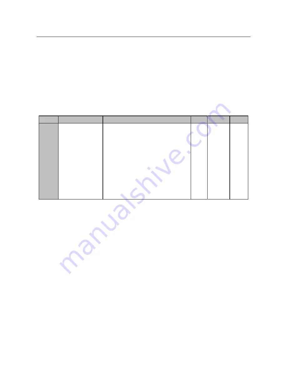
Overvoltage Protection Control
No.
Function
Range
Unit
Default
Type
FC-19
Overvoltage Stall
Control
Ones place: Not used
Tens place
:
Dynamic brake options
0: Braking resistor disabled
1: Braking resistor is enabled in operation
2: Braking resistor is enabled at power-on
Hundreds place
:
Not used
Thousands place: Overvoltage stall
protection mode
0: Disabled
1: Not used
2: Not used
0010
〇
Generally DC bus overvoltage is caused by deceleration. Due to energy feedback, DC bus
voltage will rise at deceleration. When DC bus voltage> overvoltage threshold:
If dynamic brake is enabled, built-in braking unit is switched on. External
resistor will consume part of feedback energy. Until DC bus voltage< lower limit
of overvoltage stall voltage, inverter will switch off braking unit automatically.
If overvoltage stall protection is enabled, inverter will stop deceleration
temporarily and remains output frequency unchanged, and then energy feedback
stops. Until DC bus voltage drops and be lower than lower limit of overvoltage
stall voltage, deceleration will start again. See Figure 7-13 for overvoltage stall
protection at deceleration.
The above 2 protections are enabled in all driven modes.
For the inverter with built-in braking unit, the built-in braking unit shall start
only after setting FC-19 tens place =1 or 2.


