


EM330D User Manual
A Special Purpose Inverter for Hoisting
60
F0-04=0 Keypad Control Mode
Control start/stop of inverter through
RUN
,
STOP
RESET
,
JOG
+/-
buttons on the keypad. When there is no fault,
press
JOG
+/-
to enter jog status, and press
RUN
to
enter running status. When the green LED indicator
on the
RUN
button is on, the inverter is in running
status. But when it flashes, the inverter is in
ramp-to-stop status.
F0-04=1 Terminal Control Mode
Start/Stop of inverter is controlled by Start/Stop
control terminals defined by F2
-
00
~
F2-06. When
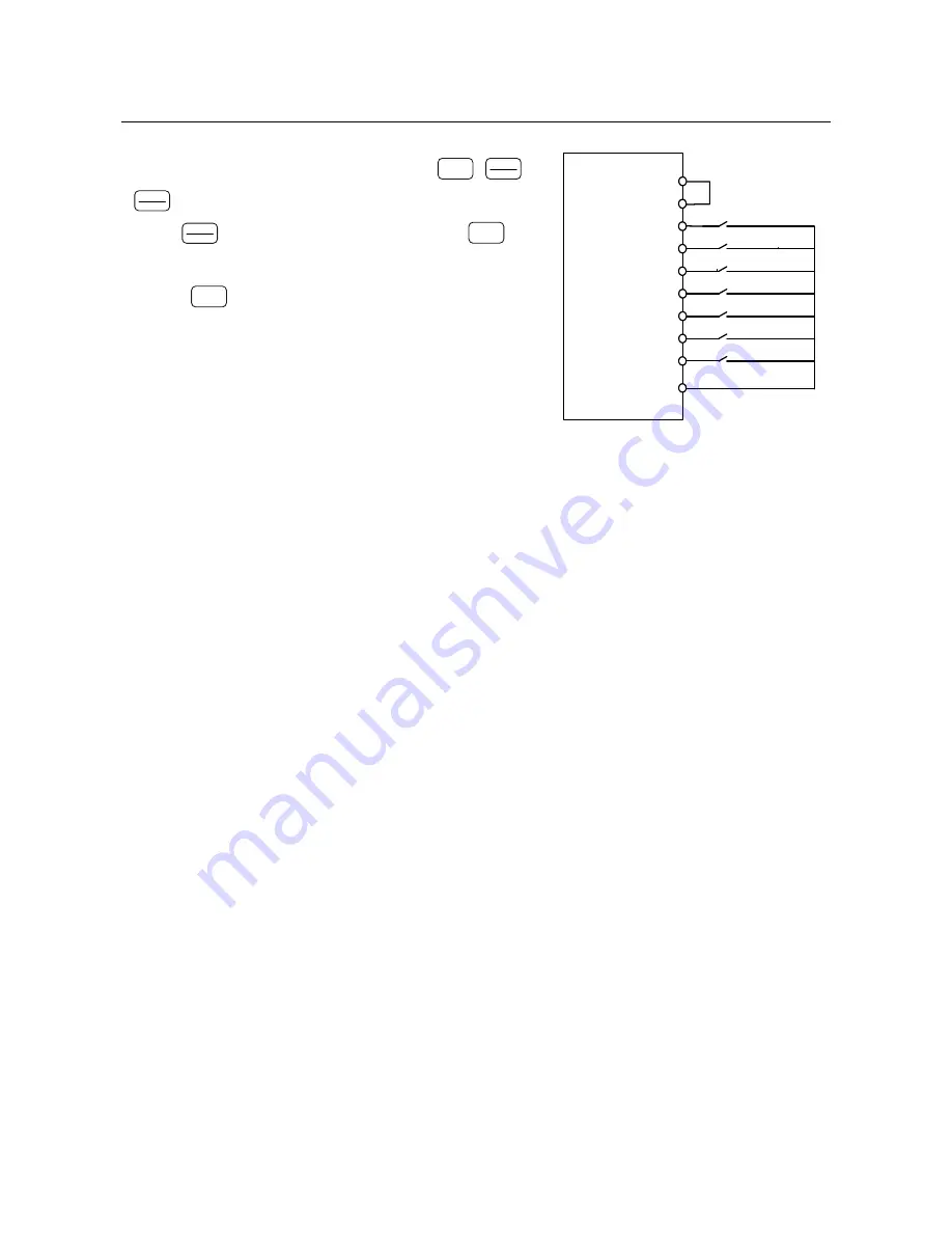
the settings of multi-function terminals are defaults, the terminal control wiring is as shown
in Figure 7-1.
The specific setting of terminal control is determined by F0
-
05.
F0-04=2 RS485 Control Mode
Start/Stop of inverter is under PC or PLC control through RS485 communication interface.
Terminal control modes can be classified as 2-wire sequence and 3-wire sequence.
2-wire sequence
:
F0-05=0
Start/stop of inverter is under control of ON/OFF of terminal RUN, and
forward/reverse of inverter is under control of OFF/ON of terminal F/R. If F0-24=1 and
reverse is prohibited, terminal F/R is off. When stop mode is selected as ramp-to-stop, the
sequence diagram is as shown in Figure 7-2 (b).
F0-05=1
Forward/stop of inverter is under control of ON/OFF of terminal RUN, and
reverse/stop is under control of ON/OFF of terminal F/R. If terminals RUN and F/R are ON
simultaneously, the inverter remains previous status. When reverse is prohibited, terminal
F/R is off. When stop mode is selected as ramp-to-stop, the sequence diagram is as shown
in Figure 7-2 (d).
RUN-Run
Preset Speed Terminal 1
F/R Forward/Reverse
Coast to Stop
Inverter Fault Reset
X1
X3
X2
X4
X5
X6
X7
PLC
24V
EM303B
Inverter
COM
Preset Speed Terminal 2
Preset Speed Terminal 3
Figure 7-1 Wiring of Terminal Control


