Copyright © Siemens AG 2016. All rights reserved
341
ERTEC 200P-2 Manual
Technical data subject to change
Version 1.0
Note: If SPI1/2_FRAME_N_a/_b is not used, the corresponding alternate function is
assigned the blocking value = '0' (see 2.3.10.8.4.2).
Notes on integration
Implementation for SPI Interface
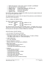
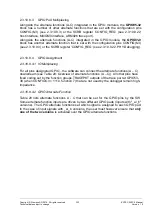
The SSPMS IP does not have a special SPI interface. The IP interface signals
SSPOE, SSPTXD, SSPRXD, SSPCTLOE, SCLKOUT, SCLKIN, SFRMOUT,
SFRMIN are therefore implemented as SPI signals (SPI_MASTER_OE_O_N,
SPI_SLAVE_OE_O_N, SPI_OUT_O, SPI_S_IN_I, SPI_M_IN_I,
SPI_SSPCTLOE_O_N, SPI_SCLKOUT_O, SPI_SCLKIN_I, SPI_SFRMOUT_O_N,
SPI_SFRMIN_I_N) as shown in the diagram above when SPI_MODE =
MISO_MOSI.
Reset
The SPI-IP can be reset by accessing a specific register. No SPI reset is required
for switching from master to slave mode. This function has already been employed
in previous projects as the IP has already be used in a number of cases. If a reset
is nevertheless required, please remember that this will lead to performance loss-
es (re-initialization).
A switchover from master to slave is required when the ERTEC 200P is connected to
another ERTEC 200P over the SPI interface for redundant connection. As the SSPMS IP
does not, according to the specifications, support dynamic toggling, it may be necessary
first to reset the IP and then set the new operating mode (master or slave).
Note on communication between SPI master and SPI slave
Communication between SPI master and SPI slave is always in full-duplex mode, i.e. it is
not possible for only the master or only the slave to send data. This means for example
that when data are only to be transferred from the SPI master to the SPI slave, the mas-
ter still clocks in the receive signal SSPRXD and enters the corresponding data words in
the receive FIFO. If the receive FIFO is not emptied, it overruns after 8 data words at the
latest and the receive overrun interrupt SSPRORINTR is triggered if enabled. (The re-
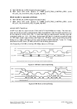
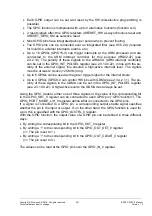
Operation without SPI_FRAME_N:
If the ERTEC 200P is connected as SPI slave to a standard controller (SPI master) that does not
support the SPI_FRAME_N signal, the ERTEC 200P is to be set as follows:
Configuration of Motorola format:
SSPCR0.FRF
= '00' (see 2.3.10.7.7)
AND
Configuration of the SPI clock phase:
SSPCR0.SPH
= '1' (see 2.3.10.7.7)
AND
GPIO pin SPI_FRAME_N (see 3.2)
Connect with ext. pull-down
OR
Connect with int. pull-down (
PULLxx_yyGPIO
= "11", see 2.3.10.9.15.2)
OR
Do not select the alternate function (blocking value = '0' is active)
Please note the following restrictions in this operating mode:
In the SPI status register,
SSPSR.BSY
(see 2.3.10.7.7) is not reset at the end of the transfer
Following a RESET (see 0), "zero data" are transferred when the first character (4-bit…16-bit,
SSPCR0.DSS
) is transferred from the SPI slave to the SPI master (return direction).


