Copyright © Siemens AG 2016. All rights reserved
123
ERTEC 200P-2 Manual
Technical data subject to change
Version 1.0
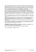
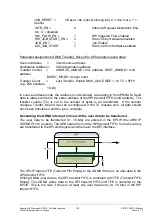
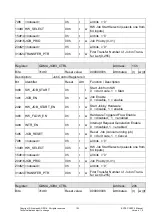
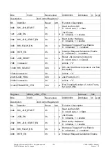
JOB_RESET =
0 Reset Job (cancel running job) 0 = don’t care, 1 =
Cancel
INTR_EN =
0
Interrupt Request Generation Ena-
ble 0 = disabled
HW_FLOW_EN
=
1
HW triggered Flow enabled
HW_JOB_START_EN
=
0
Start Job by Hardware disabled
JOB_EN =
1
Job Enable
SW_JOB_START
1
Start Job from Software enabled
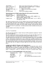
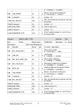
Parameter assignment of DMA Transfer_Record for SPI operation (send data):
Source Address
=
32-bit source address
Destination Address =
32-bit destination address
Transfer Control =
SOURCE_AMODE = incr. address, DEST_AMODE = hold
address,
BURST_MODE = 8-byte burst
Transfer Count =
Last Transfer, Enable DMA_ACK, ESIZE = 16, TC = 0FFh
(e.g. 256 transfers,
16-bit)
In source address mode, the address is incremented, as reading is from PN-RAM. Send
data is always written to the same address of the SPI transmit FIFO (hold address). The
transfer counter (TC) is set to the number of bytes to be transferred. If the number
changes, Tranfer_Record must be reconfigured. If the TC reaches zero, all data should
have been transferred and the job is complete.
Generating the GDMA interrupt in line with the user data to be transferred
The user data to be transferred (8…16 bits) are entered in the SPI-IP (the ARM IP
SSPMS PL021
is used). The APB enters them in the SPI transmit FIFO, from where they
are transferred to the SPI shift register and then over the SPI interface.
The SPI-IP returns TFE (Transmit Fifo Empty) to the GDMA if there is no user data in the
SPI transmit FIFO.
Writing GDMA user data to the SPI transmit FIFO is controlled with TFE (Transmit FIFO
Empty). The GDMA writes data to the SPI transmit FIFO until TFE is canceled by the
SPI-IP. This is the case if there is at least one user data entry (8…16 bits) in the SPI
transmit FIFO.


