Copyright © Siemens AG 2016. All rights reserved
459
ERTEC 200P-2 Manual
Technical data subject to change
Version
1.0
tency
Based
on
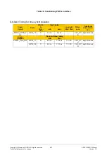
Tc = 8 ns (AHB Clock = 125 MHz);
Load-value for Timing = 20pF
Buffer Driverstrength = 12mA
IO-Voltage = 1.8V
1)
Depends on Refresh Cycle Time
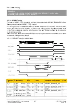
3.3.2 Host-Interface Timing
3.3.2.1 XHIF Timing
3.3.2.1.1 Separate RD/WR
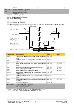
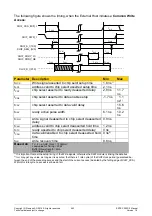
The following figure shows the timing, when the External Host initiates a
Read Access
.
Parameter Description
Min
Max
t
CSRS
chip select asserted to read pulse asserted
delay
4.4 ns
1)
t
ARS
address valid to read pulse asserted setup
time
1.9 ns
t
RRT
read pulse asserted to ready deasserted
delay
4.0 ns
11.2 ns
t
RDE
read pulse asserted to data enable delay
3.7 ns
11.4 ns
t
RAP
ready active pulse width
6.1 ns
10.1 ns
t
RTD
ready asserted to data valid delay
10.6 ns
t
RCSH
read pulse deasserted to chip select deas-
serted delay
1.3 ns
2)
t
RAH
address valid to read pulse deasserted hold
time
1.1 ns
t
RDH
data valid/enable to read pulse deasserted
hold time
2.4 ns
11.7 ns
t
RR
read recovery time
12.4 ns
Based on
Tc = 8 ns (AHB Clock = 125 MHz);
Load-value for Timing = 20pF
Buffer Driverstrength = 9mA
IO-Voltage = 3,3V
1)
If t
CSRS
< 0, t
ARS
, t
RRT
and t
RDE
are related to the falling edge of XHIF_XCS
2)
If t
RCSH
< 0, t
RAH
and t
RDH
are related to the rising edge of XHIF_XCS

