Copyright © Siemens AG 2016. All rights reserved
236
ERTEC 200P-2 Manual
Technical data subject to change
Version 1.0
2.3.8.2.1 Status of the integrated PHY
2.3.8.2.1.1 PHY Status LED
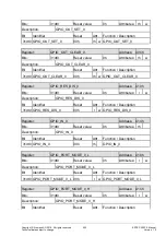
The following PHY status LEDs are connected to the pinning (see 3.2):
Dedicated PHY LEDs:
-
P1/2_XLINK_STATUS (Link / No Link)
-
P1/2_XACITVITY (Receive or Transmit Activity / No Activity)
These LED outputs can be controlled directly from the multiport PHY. P1/2_XActivity
combines the receive and transmit activity outputs of the multiport PHY. Alternatively,
these LED outputs can also be controlled by the SW. SW control is with the
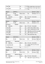
PHY_LED_CONTROL register in the SCRB (see 2.3.10.9.22). The status of the PHY
outputs 'P1/2_XLINK_STATUS / P1/2_XACITVITY' can also be queried with the
PHY_LED_ CONTROL register if the SW is controlling the LEDs.
2.3.9 CRU (Clock and Reset Unit)
2.3.9.1 Clock System
The ERTEC 200P clock system consists primarily of four clock groups which are isolated
with asynchronous crossings. These systems are as follows:
ARM926EJ-S processor system
JTAG interfaces
AHB system, APB system, PN-IP and PER_IF
Host interface (parallel: XHIF, serial: host SPI)
PHYs + Ethernet MACs
2.3.9.2 Clock Generation and Distribution
The ERTEC 200P clocks required are provided over internal PLL and/or with direct sup-
ply. Apart from the JTAG clock and the PHY clock, all clocks are generated by the inte-
grated PLL.
MODULE
CLOCK SOURCE
FREQUENCY
ARM926ES
PLL
250/125 MHz
AHB/EMC/ICU/HOST-IF/GDMA
PLL
125 MHz
PN-IP (except MAC MII/GMII)
PLL
125/250 MHz
PER_IF
PLL
125 MHz
APB
PLL
125 MHz
JTAG
JTAG clock
16/32 MHz
MAC MII/GMII / PHY
CLKP_A / external
25/125 MHz
Table 16: Overview of ERTEC 200P clocks
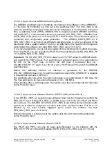
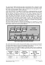
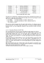
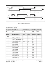
In ERTEC 200P, the clock is distributed to the various modules. The PHYs start in the
disable state and must be enabled by the SW.

