Copyright © Siemens AG 2016. All rights reserved
243
ERTEC 200P-2 Manual
Technical data subject to change
Version 1.0
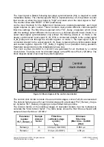
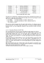
2.3.9.4.1
Asynchronous PowerOn Reset
The asynchronous
PowerOn reset is connected to the ERTEC 200P with the XRESET
pin. In response to this reset, the complete circuit (incl. clock system) of the ERTEC 200P
is reset and the configuration pins are latched (see 2.3.10.9.3
). The PowerOn reset must
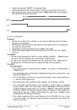
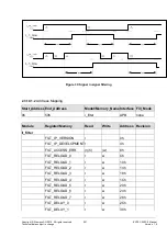
be applied steadily for at least 30µs after a steady voltage is reached upon ERTEC 200P
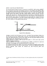
startup. The PLL then starts up and after a further 1000 µs, the PLL is locked. This time
until the PLL locks is t
LOCK
. Internally, the PowerOn reset phase is extended by this time
(fixed setting; the PLL lock is not evaluated) and the clock system is not connected until
the end of the startup phase. The internal reset remains active for a further 16 clocks
after clock system startup to execute the reset internally. Debugger communication over
the JTAG interface is not possible during this time.
Figure 29:
PLL startup phase
Hardware monitors the locked state of the PLL. The IRQ49 interrupt signals whether the
PLL has lost its input clock (quartz break) or the PLL is not locked (PLL monitor, monitors
input and output frequency). The two error states can also be queried directly from the
SCRB register 'PLL_STAT_REG' (see 2.3.10.9.22
X
).
A filter integrated in ERTEC 200P ensures that spikes <= 40 ns (best case) at the
XRESET input are suppressed.
While the XRESET pin is active, the bidirectional pin XSRST is switched to output and
activated. The debugger can then detect the PowerOn reset phase.
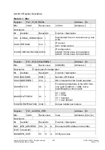
The PWRON_HW_RES bit in RES_STAT_REG is set during a PowerOn reset to allow
an analysis of the reset event after a system restart. This bit is not affected by the reset
function triggered. Upon restart, the software can read RES_STAT_REG (see
2.3.10.9.22
X
).
6
An asynchronous reset affects the reset input of a flip-flop. This reset is applied asynchronously but cleared synchro-
nously.

