Copyright © Siemens AG 2016. All rights reserved
108
ERTEC 200P-2 Manual
Technical data subject to change
Version 1.0
2.3.4.1.3.4
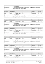
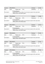
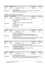
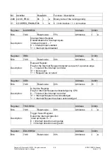
DMA Job Control registers
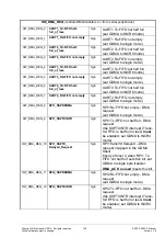
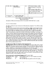
A Job Control register consists of the following fields:
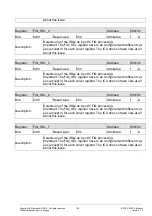
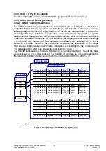
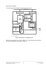
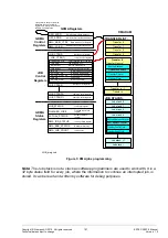
First Transfer Number of the Job (TRANSFER_PTR) is a pointer to the
transfer number of the first transfer of the job. (The pointer is shown in Fi-
gure 3)
Job Priority (JOB_PRIO) defines the priority of the job. A higher value of
JOB_PRIO means higher priority. If two or more jobs have the same value
of JOB_PRIO, then the job priority is defined by the job number. In such a
case, the smaller job number means the higher priority. When e.g. the
JOB_PRIO field has the same value for each job, the highest priority has
the started job with the smallest job number.
HW Job Start Selector (HW_SELECT) defines, which of „n” HW job-
starting signals is chosen to start the job by HW. Note that the maximum
number of job-starting input signals is parameterizable up to 64. The HW
parameter has no influence on the register width.
Job reset (JOB_RESET) cancels the running job.
Interrupt request generation enable (INTR_EN) enables GDMA controller
to generate interrupt request when the job has finished.
Hardware Triggered Flow Enable (HW_FLOW_EN) enables/disables the
check whether the HW peripheral is ready.
Start Job by HW enable (HW_JOB_START_EN).
Enable Job (JOB_EN) enables the run of the Job or interrupts the running
job.
Start Job by SW (SW_JOB_START).
2.3.4.1.3.5 Transfer list
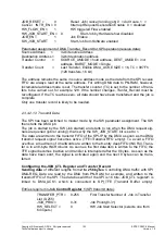
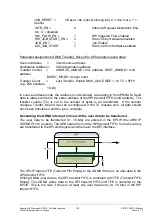
The DMA RAM’s transfer record defines all parameters of a single DMA trans-
fer and consists of four 32-bit words:
“Source Address” defines the address of source data for the DMA transfer.
This can be either a memory or a peripheral address.
“Destination Address” defines the address of the destination for the DMA
transfer. This can be either a memory or a peripheral address. The ad-
dresses of the GDMA registers and DMA RAM are protected against write
accesses
by
the
DMA
transfers.
The reason for this is as follows: When the GDMA controller is pro-
grammed incorrectly, the data in the GDMA registers and DMA RAM could
be corrupted and subsequently the system might fail. When a wrong desti-
nation address is programmed, then the DMA destination address error is
assumed. When at the same time bit “Error Interrupt Enable”
(ERR_INT_EN) in the GDMA Main Control register is “1”, the relevant error

