Copyright © Siemens AG 2016. All rights reserved
119
ERTEC 200P-2 Manual
Technical data subject to change
Version 1.0
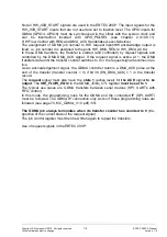
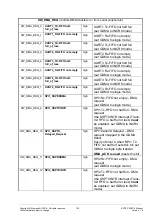
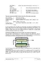
Not all HW_JOB_START signals are used in the ERTEC 200P. The input signals for the
HW_JOB_START inputs that are not used are set to inactive level. The GPIO inputs for
GDMA (GPIO3...GPIO0) must be synchronized in the I-filter with the system clock and
can be inverted/not inverted with GPIO_POLSEL (see chapter 2.3.10.9.11).
HW Flow Control with REQ and DMA_ACK Handshake (Level-Sensitive)
The assignment of GDMA job number to HW request input/HW acknowledge output is
fixed, i.e. job number 4 is assigned to the ports HW_DMA_REQ4 / HW_DMA_ACK4.
In these DMA transfers, the transfer is started (and controlled) by request signals and
controlled by the DMA DMA_ACK signal. If the request signal is active at 1, the DMA
transfers data until the transfer counter switches to 0 or the request signal becomes inac-
tive.
As an acknowledgement signal, the GDMA controller returns a DMA_ACK pulse at the
end of the transfer (transfer counter = 0) if bit 30 (EN_DMA_ACK) = 1 in the transfer
record.
The
request
signal must also have the
state 1
(active level) for
the ACK
signal
to be
output
. The
HW_FLOW_EN
bit in the
GDMA_JOBx_CTL
register
must be set to 1.
The typical use cases are GDMA transfers between serial devices (SPI, UARTs with
FIFO control)
In this mode, the programming rules for the GDMA and the connected IP (SPI, UART)
must be followed. The GDMA IP connection only works if these programming rules are
followed (see page 70, MC_GDMA_V1.0.pdf) /55/.
The GDMA job always terminates when its transfer counter has counted to 0
(irre-
spective of the current state of the request signal).
The job control register must then be written again to repeat the transfers.
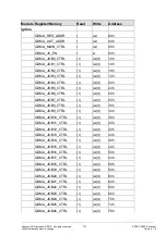
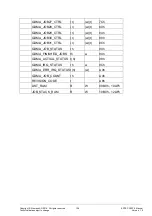
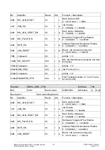
Use of request signals in the ERTEC 200P:

