Copyright © Siemens AG 2016. All rights reserved
14
ERTEC 200P-2 Manual
Technical data subject to change
Version
1.0
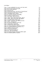
List of Tables
Table 1: Types of ARM926EJ-S access to I/D-TCM / AHB
Table 2: Boot, ERTEC 200P boot modes
Table 3: Boot mode adjustment
Table 4: Startup Times
Table 5: Internal bus system, parameters of internal buses
Table 6: Fixed priority assignment (no default)
Table 7: AHB Master-slave coupling
Table 8: Access Error Register (from SCRB)
Table 9: Host INTA, Interrupt sources
Table 10: Host INTB, Interrupt sources
Table 11: DMA, Table of HW_JOB_START_Signals
Table 12: DMA, Table of HW_DMA_REQ-Signals
Table 13: The DMA RAM address space.
Table 14: EMC, Connection to the Memory devices
Table 15: EMC – Address map
Table 16: Overview of ERTEC 200P clocks
Table 17: Data width of peripherals
Table 18: Sample filter times for I-filter
Table 19: Timing parameters for SPI flash (75 MHz)
Table 20: Overview of alternate functions (A – C)
Table 21: ERTEC 200P, ID register
Table 22: Bootmodi adjustment
Table 23: Configuration adjustment
Table 24: IO – pin count overview
Table 25: Signal Description and Pinning ERTEC 200P
Table 26: Constraining PNPLL Interface


