Copyright © Siemens AG 2016. All rights reserved
372
ERTEC 200P-2 Manual
Technical data subject to change
Version 1.0
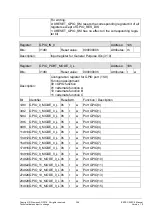
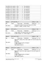
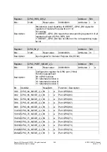
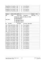
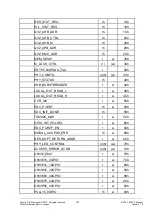
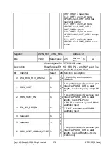
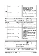
PULL15_0GPIO: Covers the GPIO15..0
pads
PULL31_15GPIO: Covers the GPIO31..15 ads
PULL47_32GPIO: Covers the GPIO47..32 pads
PULL63_48GPIO: Covers the GPIO63..48 pads
PULL79_64GPIO: Coves the GPIO79..64 pads
PULL95_80GPIO: Covers the GPIO95..80 pads
The following combinations can be set for each GPIO pad:
Coding
Pull
00b
highZ
01b
Pull-Up
10b
highZ
11b
Pull-
Down
The pull setting is only effective if the pad is connected to the input. If the pad is operating
as an output, the pull is deactivated. The pulls have a resistance of 35 – 65 k (typ. 50
, see 0).
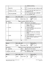
During / following a reset, the pull settings in the registers are preassigned. The reset
values can be found in the register description. With GPIO95..0, there is also a depend-
ency on the CONFIG6:3 pins. Different pull settings are used during / after a reset for the
7 different modes. The settings can be changed by the SW at any time.
Important: The pull setting does not change automatically following reconfiguration of the
CONFIG6..3 bits in CONFIG_REG by the SW. It must be changed by the SW.
2.3.10.9.15.3
Reset Behavior of EMC Pins without Pull Circuit
Some of the ERTEC 200P EMC output pins have no internal pull resistors:
CLK_O_SDRAM2
*)
CLK_O_BF0 – 2
*)
CLK_O_SDRAM0-1 are by default connected in line with DRIVE_EMC(22) (see 2.3.10.9.22) and are therefore not
high-impedance during a reset
Remember this when connecting external components, as these pins become high-
impedance during a reset and produce floating input signals at the other components.
Blocks whose inputs are connected to these ERTEC 200P EMC output pins without in-
ternal pull resistors must if necessary be protected from a floating input voltage with ex-
ternal pulls.

