Copyright © Siemens AG 2016. All rights reserved
337
ERTEC 200P-2 Manual
Technical data subject to change
Version 1.0
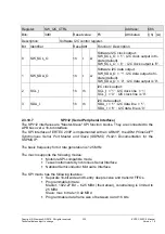
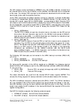
SSPCTLOE (Output): Output enable signal for SCLKOUT and SFRMOUT
SSPTXD (OUTPUT): Serial data (Output:
SSPOE (Output):
Output enable signal when SSPTXD is valid
SFRMIN (Input):
Serial Frame Input (Slave)
SCLKIN (Input):
Serial Clock Input (Slave)
SSPRXD (Input):
Serial Data Input
If the SPI1/2 output signals are enabled at the GPIO, they drive the outputs directly and
are not subject to output enable control.
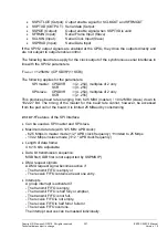
The following baud rates apply for the clock output of the synchronous serial interfaces in
line with the SPI1/2 parameters.
F
CLKOUT
= 125MHz / (CPSDVR*(1+SCR))
The following applies for the parameters:
SPI master: CPSDVR := (2..254), multiples of 2 only
SCR
:= (0..255)
SPI slave: CPSDVR := (4..254), multiples of 2 only
SCR
:= (2..255)
This produces baud rates ranging from 62.5 MBd (master) / 10.42 MBd (slave) down to
1922.27 Bd. The timing of the master for this baud rate cannot, however, be accessed
from the pad cell or the board; it is limited 25 MBaud by constraining.
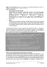
2.3.10.7.1
Features of the SPI Interface
Can be used as SPI master and SPI slave.
Maximum data rate (with 125 MHz APB clock):
- 62.5 Mbps in master mode (1/2 * APB clock frequency)
limited to 25 Mdps
- 10.42 Mbps in slave mode (1/12 * APB clock frequency)
Length of data frame:
4 to 16 bits, adjustable
Data bit transmission sequence:
MSB first (LSB first is not supported by SSPMS IP)
DMA request signals
A DMA request signal becomes active if
- The transmit FIFO is empty or
- The receive FIFO contains at least one entry.
Interrupts
A group interrupt is activated if
- The transmit FIFO is empty,
- The transmit FIFO is half fully or emptier,
- The transmit FIFO is not full,
- The receive FIFO is not empty,
- The receive FIFO is half full or fuller or
- The receive FIFO overruns.
The interrupt sources can be masked individually.

