3-40
3
Operation Examples (Point measurement)
Press the TRG/BRT key on the
remote key pad, and the level
(brightness of the screen) will be
switched between H and L.
3
1
5
F C1 H
Indicates camera 1.
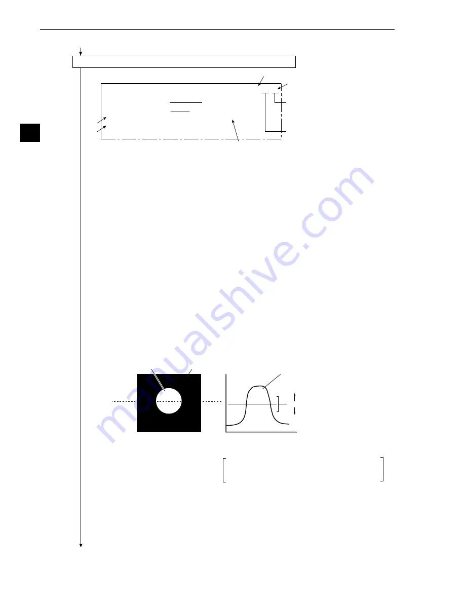
[MEASURING COND] (TYPE00-MEAS1-POINT-MEAS)
1
PROCESSING MODE BIN-CONV AV-LIGHT-LEVEL
2
BINARY CONV COND FIXED THRESHOLD-ADJ
3
THRESHOLD VALUE U.LM
−
255
L.LM
−
100(0~255)
4
SET POINT
(TO NEXT SUB-MENU)
5
UPPER MENU
4
7
White
Inspection image
Horizontal coordinate
of the dotted line
Changing the lower limit threshold
The size of the white area changes
depending on the threshold setting.
As the value increases,
the black part grows larger.
Stable range
As the value decreases,
the white part grows larger.
0
255
White
*
*
Black
Lower limit threshold
If the stable range in the lower limit threshold
is less than 20, (actual measurement)
measurement errors may occur.
Continued from the preceding page
(5) Operation on the [MEASURING COND] menu (image adjustment)
1. Press the SEL key.
-
The image taken by camera 1 will be displayed.
- If the image is so bright that the menu is hard to see, press the TRG/BRT key to reduce the
brightness of the image. Then, the brightness indicator in the upper right corner of the
screen will change from H to L.
2. Adjust the focus and aperture (iris) opening of the camera lens (see page 5-1), so that the
object to be measured is clear and easily destinguished.
3. Press the SEL key to enter the freeze image mode.
-
The indicator in the upper right corner of the screen will change from T (through) to F
(freeze).
- To store a threshold value in the following step, the screen must enter the free image
mode. (See section 7-2 "Screen specifications" for the through/freeze mode.)
4. Move the cursor to
3
THRESHOLD VALUE (threshold value) with the up and down keys,
and press the SET key.
-
An binary image of the reference object will be displayed.
5. Move the cursor to the lower limit with the left and right keys, and adjust the lower limit
threshold value with the up and down keys.
(Adjustment of threshold)
An example of adjustment is shown below, using a white object on a black background. When
the dotted line in the window is converted to a binary image, if the lower limit is set higher, the
black part in the binary image will become larger. If the lower limit is set lower, the white part
will become larger. Increase and decrease the lower limit value, find the value at which the
white part in the binary image starts growing and the value at which the black part starts
growing. Then set the lower limit at the value halfway between these points.This will ensure
reliable operation.
6. After setting the lower limit, press the SET key.
7. Move the cursor to
4
SET POINT (setting point) and press the SET key.
-
The point setting menu will be displayed.
Continued on the following page


