3-33
3
Operation Examples (Lead inspection)
Continued from the preceding page
(6) Image adjustment
1. Press the SEL key.
-
The image taken by camera 1 will be displayed.
- If the image is so bright that the menu is hard to see, press the TRG/BRT key to reduce
the brightness of the image. Then, the brightness indicator in the upper right corner of
the screen will change from H to L.
2. Adjust the focus and aperture (iris) of the camera lens (see p.5-1), so that the object to be
measured is clear and easily distinguished.
3. Press the SEL key to enter the freeze image mode.
-
The indicator in the upper right corner of the screen will change from T (through) to F
(freeze).
- To store an image for the following gray scale search matching setting operations, the
screen must be in the freeze image mode. (See section 7-2 "Screen specifications" for
details about the through/freeze mode.)
(7) Operation for the gray scale search matching setting
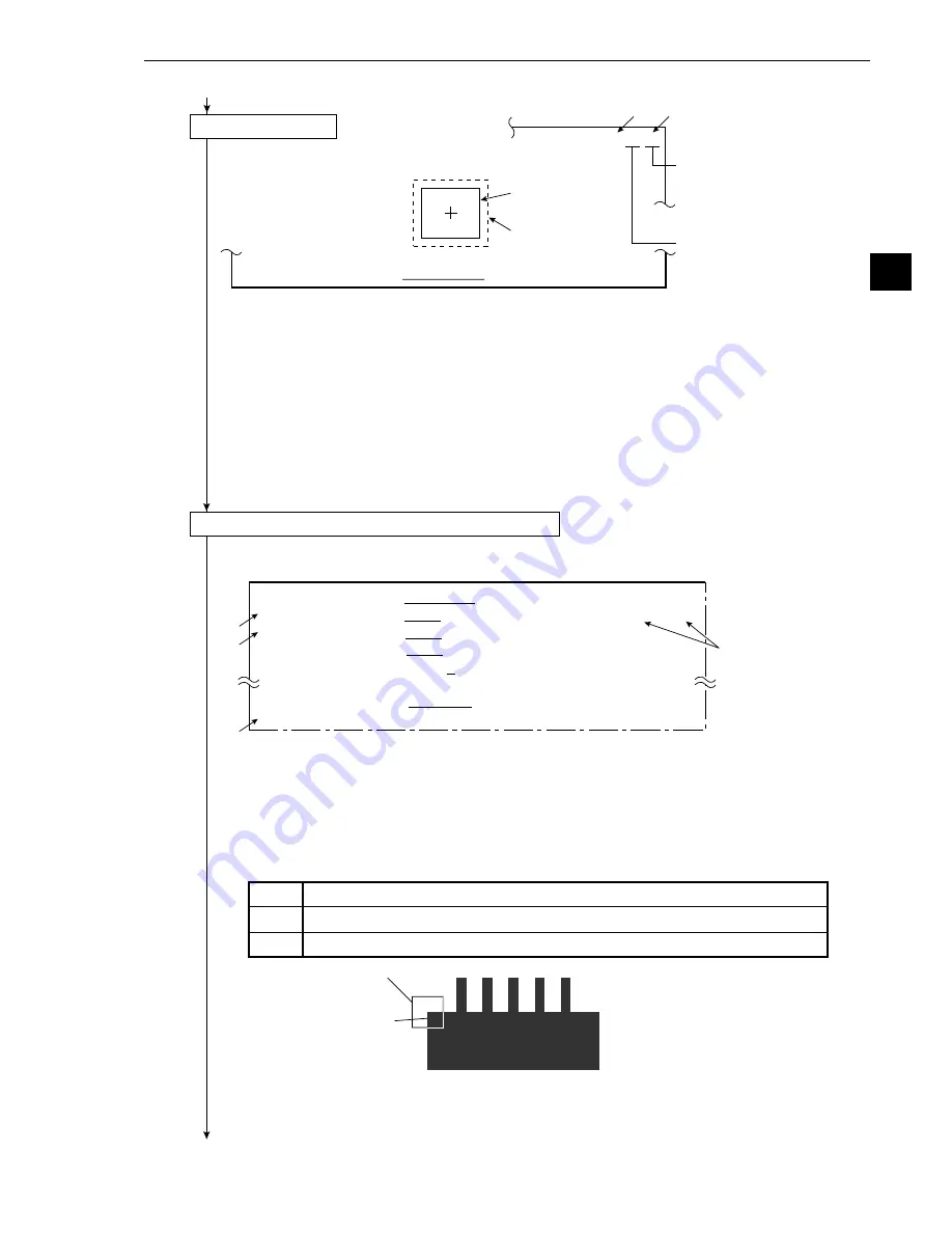
1. Press the ESC key, and all of the menus used for setting the gray scale search conditions will
be displayed.
· If the menu overlaps the image to be measured so that further image setting is hindered,
press the ESC key. Only item
1
will be displayed.
2. Move the cursor to
2
REFERENCE IMAGE using the up and down keys, and press the SET
key.
3. Surround the image for correction of detection line in the image window (solid line).
- Move the cursor to MOVE, UP.L or LO.R with the right and left keys, and press the SET key.
Then, position the window.
When the position is correct, press the SET key.
4. After the image window position has been defined, move the cursor to REG. (registration)
with the right and left keys, and press the SET key.
- Move the cursor to DISP (display) with the left and right keys, and press the SET key. Then,
the stored image will be displayed in the lower right corner of the screen. After checking the
image, press the ESC key.
Continued on the following page
Press the TRG/BRT key on
the remote key pad, and the
level (brightness of the
screen) will be switched
between H and L.
Indicates camera 1.
Image window
Search window
3
1
F C1 H
1
MEASURE WINDOW RECTANGLE
X-LINE
Y-LINE
8
4
5
2
1
MEASURE WINDOW RECTANGLE
X-LINE
Y-LINE
2
REFERENCE IMAGE MOVE
UP.L(224,208
)
LO.R(287,271
)
REG. DISP
3
SEARCH AREA
MOVE UP.L(216,200
)
LO.R(295,279)
4
DETECTED COORD CNTR
FREE(256,240)
5
CONTRACT PIXELS 1
2
3
q
DETECT ACCURANCY STANDARD
HIGH
w
UPPER MENU
Image for correcting
the detection line
Image window
MOVE
The white rectangle is moved using the up, down, right or left key (4 pixels at a time).
UP.L
The upper left corner is moved using the up, down, right or left key (4 pixels at a time).
LO.R
The lower right corner is moved using the up, down, right or left key (4 pixels at a time).


