ELEC
Electrical system
–
+
8-29
6AL3J11
8.
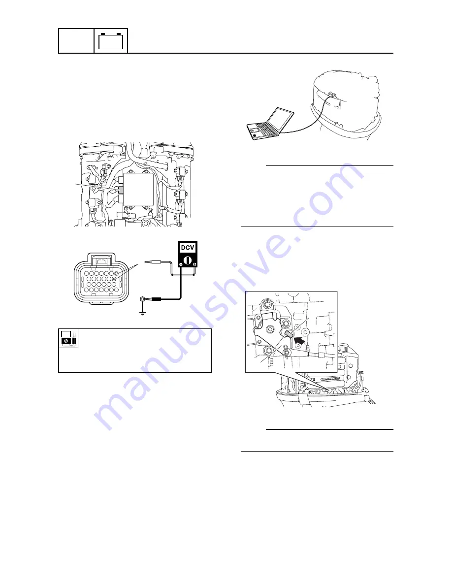
Disconnect the ECM coupler
a
.
9.
Turn the engine start switch to
“
ON,
”
and
then measure the input voltage at ECM
coupler terminals
f
(27 and 34, wiring
harness end) and ground. Check the
fuse, relay, and wiring harness if below
specification.
10. Turn the engine start switch to
“
OFF.
”
11. Connect the ECM coupler
a
.
Checking the accelerator position
sensor
1.
Connect a computer to the outboard
motor and use the YDIS to display
“
Accelerator position sensor 1
”
and
“
Accelerator position sensor 2.
”
NOTE:
•
Accelerator position sensor 1 and accelera-
tor position sensor 2 are a single unit,
which cannot be disassembled.
•
To connect and operate the YDIS, see
Chapter 9,
“
YDIS
”
and the YDIS (Ver. 1.23a
or later) Instruction Manual.
2.
Check that the accelerator lever
1
con-
tacts the fully closed stopper
2
when the
remote control lever is at the fully closed
position.
NOTE:
To adjust the throttle cable, see Chapter 3,
“
Adjusting the throttle cable.
”
3.
Turn the engine start switch to
“
ON,
”
operate the remote control lever, and
then check the output voltages of accel-
erator position sensor 1 and accelerator
position sensor 2 at the fully closed posi-
tion
a
and fully open position
b
.
Terminal
f
(R/Y):
Q
–
Ground
X
–
Ground
12 V (battery voltage)
S6AL8900
a
S6AL8590
f
a
S6P24140
2
1
S6P21030
Summary of Contents for Fin Whale 225 EFI
Page 1: ...Grey Whale 200 EFI Fin Whale 225 EFI SERVICE MANUAL...
Page 4: ......
Page 87: ...6AL3J11 4 18 1 2 3 4 5 6 7 8 9 S6AL4240 7 8 Throttle body...
Page 183: ...6AL3J11 5 82 1 2 3 4 5 6 7 8 9 MEMO Cylinder block...
Page 364: ...ELEC Electrical system 8 53 6AL3J11 MEMO...
Page 397: ......
Page 398: ......


