


SMIQ
Rear Panel
1125.5555.03
2.15
E-7
11
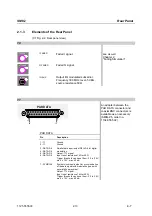
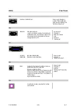
PAR DATA
Pin
Description
8 -
⊥
Ground
9 - LEV-ATT
Signal input/output for controlling of level
reduction.
Output: TTL signal.
Input: Input resistance 1k
Ω
or 50
Ω
.
Trigger threshold can be set from -2.5 to 2.5V,
max. ± 15V, max. 40 mA
10 -
⊥
Ground
11 - TRIGOUT 1
Output for triggering of external instruments.
Output: TTL signal.
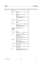
12 -
⊥
13 -
⊥
Ground
Ground
14 - TRIGIN
Input for triggering of frames, PRBS and data
sequences.
Input: Input resistance 1k
Ω
or 50
Ω
.
Trigger threshold can be set from -2.5 to 2.5V,
max. ± 15V, max. 40 mA
15 - DATA-D7
16 - DATA-D5
17 - DATA-D3
18 - DATA-D1
Parallel data input/output D1to D7
see pin 3 - 6
19 -
⊥
Ground
20 - BITCLK
Output bit clock with operating mode internal.
TTL signal
21 - CW
Signal input/output for controlling of
modulation. Switches carrier to CW with FSK
modulation.
Output: TTL signal.
Input: input resistance 1k
Ω
or 50
Ω
.
Trigger threshold can be set from -2.5 to 2.5V,
max. ± 15V, max. 40 mA
22 - BURST-
GATE
Signal input/output for controlling of the burst
profile.
Output: TTL signal.
Input: input resistance 1k
Ω
or 50
Ω
.
Trigger threshold can be set from -2.5 to 2.5V,
max. ± 15V, max. 40 mA
23 - TRIGOUT 2
Output for triggering and controlling of external
instruments.
Output: TTL signal.
24 - TRIGOUT 3
Output for triggering and controlling of external
instruments.
Output: TTL signal.
25 - HOP
HOP output provides control signal when
internal frequency hopping is programmed.
Output: TTL signal


