


Digital Modulation
SMIQ
1125.5555.03
E-9
2.90
Table 2-9
Coding algorithms
CODING
Coding algorithm
Applicable for K bit/symbol
NONE
dc
n
= d
n
K = 1 to 8
DIFF
dc
n
= (d
n
+ dc
n-1
) modulo 2k
K = 1 to 7
GRAY+DIFF
Gray coding with additional differential coding
K = 1 to 7
GSM
dc
n
= not (d
n
exor d
n-1
K = 1
VDL
VDL standard
K = 3
Example 1:
Differential coding for QPSK modulation with K = 2 bit/symbol
Decimal display; value range for modulation symbols
{
}
d
n
∈
012 3
; ; ;
Recursive coding is defined as follows: dc
n
= (d
n
+ d
cn
-1) modulo 4.
Depending on the state of a preceding modulation symbol dc
n-1
the coded modulation
symbol dc
n
is obtained for example from a modulation symbol d
n
= 2 as follows:
d
n
= 2
dc
n-1
dc
n
0
2
1
3
2
0
3
1
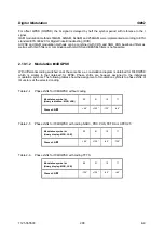
By means of differential coding, the assignment between modulation symbols and
phase differences shown in the following table is generated:
Modulation symbol d
n
(binary, MSB, LSB)
00
01
10
11
Phase difference
∆ϕ
0°
90°
180°
270°
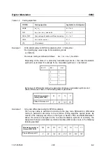
Example 2:
Gray and differential coding for 8PSK modulation
First, a gray coding is performed according to the gray code. Afterwards, a differential
coding is performed according to the recursive coding algorithm quoted above. By
means of the mapping rule shown in the figure in Section 'PSK and QAM Modulation'
above, IQ values are assigned to the re-coded modulation symbols. In summary, the
assignment between modulation symbols and phase differences shown in the following
table is generated:
Modulation symbol d
n
(binary, MSB, LSB)
000
001
010
011
100
101
110
111
Phase difference
∆ϕ
0°
45°
135°
90°
270°
315°
225°
180°


