


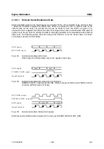


Fading Simulation
SMIQ
1125.5555.03
2.84
E-9
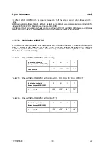
INSERTION LOSS
SETTING MODE
Selection of a setting mode for the insertion loss of the fading simulator.
See explanation under STANDARD FADING.
IEC/IEEE-bus command
:SOUR:FSIM:BIRT:ILOS:MODE NORM
:SOUR:FSIM:BIRT:ILOS:MODE LACP
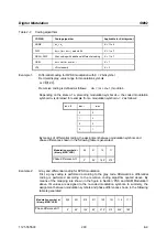
SET DEFAULT
Sets the default setting of the path parameters.
IEC/IEEE-bus command
:SOUR:FSIM:BIRT:DEF
PATH
Indicates the paths for subsequent parameters. These parameters can be set
individually for each path.
PROFILE
Selection of a fading profile. Only pDOPP is available here; when FREQ
RATIO = 0 is set a "non-fading“ path is obtained.
pDOPP
(pure DOPPler) Simulation of a transmission path having a single
direct connection from the transmitter to the moving receiver
(discrete component).
The Doppler frequency shift is determined by the parameters
DOPPLER FREQ and FREQ RATIO.
IEC/IEEE-bus command
:SOUR:FSIM:BIRT:PATH1:PROF PDOP
FREQ RATIO
Entry value of ratio of actual Doppler frequency shift. See explanation under
STANDARD FADING. When FREQ RATIO = 0 is set, a "non-fading" path is
obtained.
IEC/IEEE-bus command
:SOUR:FSIM:BIRT:PATH1:FRAT 1
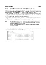
SPEED
Entry value of the speed v of the moving receiver.
See explanations under STANDARD FADING.
All entries in path 1 are copied for path 2.
IEC/IEEE-bus command
:SOUR:FSIM:BIRT:PATH1:SPE 100
DOPPLER FREQ
Entry value of the magnitude of the maximum Doppler frequency shift. See
explanation under STANDARD FADING.
All entries in path 1 are copied for path 2.
IEC/IEEE-bus command
:SOUR:FSIM:BIRT:PATH1:FDOP 92.3
PATH LOSS
Entry value of attenuation in path. Value range: 0.0 to 50.0 dB.
IEC/IEEE-bus command
:SOUR:FSIM:BIRT:PATH2:LOSS 3
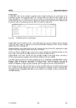
DELAY
Entry value of signal delay in path 1. All entries in path 1 are copied for path 2.
Value range: 5.0 to 1000.0
µ
s.
IEC/IEEE-bus command
:SOUR:FSIM:BIRT:PATH1:DEL 1000 E-3
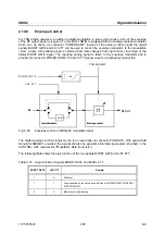
DELAY RANGE
The delay of the two paths is within this range.
Non-editable parameter.
For the two channels: -5.0 to +5.0
µ
s.
DELAY GRID
Time grid of the different carriers appearing at random. The carriers have
delays which lie within the DELAY RANGE and coincide with
n * DELAY GRID (with n –5 to +5).
Non-editable parameter. Value = 1 µs for the two channels.
HOPPING DWELL
Dwell period until the next BIRTH-DEATH action. After this dwell period the
next path changes its delay at random.
Value range: 100.0 to 5000.0 ms.
IEC/IEEE-bus command
:SOUR:FSIM:BIRT:PATH1:HOPP:DWEL 1.2


