background image

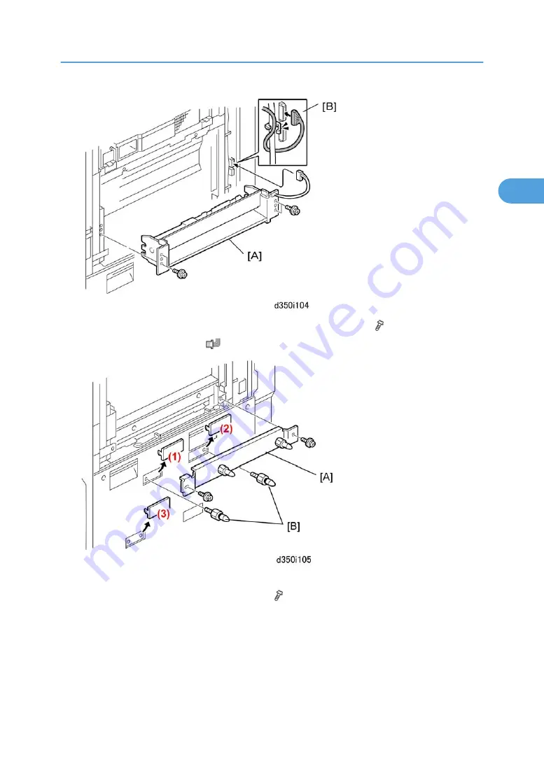
9. Use the screws removed with the bypass tray to attach the relay unit [A] ( x4).

10. Connect the relay harness [B] (

 x1).

11. Remove knockouts: (1), (2), (3).
12. Attached the stay [A] with the provided screws (  x2).
13. Attach the joint connection pins [B] (x2).
14. Re-attach the right upper cover.

LCIT RT4000 (D350)

137

2

Summary of Contents for V-C3 D081

Page 1: ...Model V C3 Machine Code D081 D082 Field Service Manual 30 November 2009...

Page 2: ......

Page 3: ...Conventions Symbol What it means Core Tech Manual Screw Connector E ring C ring Harness clamp FFC Flexible Film Cable The notations SEF and LEF describe the direction of paper feed The arrows indicate...

Page 4: ...zardous situation Failure to obey a Warning could result in death or serious injury A Caution indicates a potentially hazardous situation Failure to obey a Caution could result in minor or moderate in...

Page 5: ...fers to the Z Folding unit The Z Folding unit is available in Japan only ITB Image Transfer Belt PTR Paper Transfer Roller General Safety Instructions For your safety please read this manual carefully...

Page 6: ...tenance Shipping and Moving the Machine Work carefully when lifting or moving the machine If the machine is heavy two or more customer engineers may be required to prevent injuries muscle strains spin...

Page 7: ...ts etc removed for installation have been removed and that no tools remain inside the machine This also ensures that all release interlock switches have been restored to normal operation Never use you...

Page 8: ...n small amounts to avoid breathing the fumes and becoming nauseous Switch the machine off unplug it and allow it to cool before doing preventive maintenance To avoid fire or explosion never use an org...

Page 9: ...fire Inspect the length of the power cord for cuts or other damage Replace the power cord if necessary A frayed or otherwise damaged power cord can cause a short circuit which could lead to a fire or...

Page 10: ...med paper and troubleshoot other minor problems by following the procedures described in the operating instructions Point out the parts inside the machine that they should never touch or attempt to re...

Page 11: ...er cartridges or toner bottles including empty toner bottles or cartridges in a location where they will be exposed to high temperature or an open flame Always store toner and developer supplies such...

Page 12: ...l to avoid touching those components with your bare hands 7 To prevent a fire or explosion keep the machine away from flammable liquids gases and aerosols Health Safety Conditions 1 Never operate the...

Page 13: ...the field The optical housing unit can only be repaired in a factory or at a location with the requisite equipment The laser subsystem is replaceable in the field by a qualified Customer Engineer The...

Page 14: ...werPC is a registered trademark of International Business Machines Corporation Other product names used herein are for identification purposes only and may be trademarks of their respective companies...

Page 15: ...feature an automatic voltage detection function Model Voltage Table Model Area Voltage D081 17 NA 110 127 V 20 A 60 Hz D082 17 NA 208 240 V 12 A 60 Hz D081 19 27 29 D082 19 21 27 29 EU AP TWN 220 240...

Page 16: ...d on the right end of the operation panel There are still slots on the control board at the back of the machine but this new option provides easier access to the USB and SD card slots at the front of...

Page 17: ...time a 90 s b 75 s a 70 s b 60 s Much shorter warm up time First copy time BW a 5 7 s b 4 9 s a 5 7 s b 4 9 s First copy time FC a 7 5 s b 6 4 s a 7 5 s b 6 4 s Two New Options The Multi Fold Unit D45...

Page 18: ...y duplexing ADF Simultaneous 2 side scanning with CIS scanning the rear side without duplex feeding Fusing unit Employs hot roller pressure roller heating roller with cleaning unit Employs nearly iden...

Page 19: ...ot access Controllerboxatrearofmain machine A new option installed on right end of operation panel allows slot access at the front of the main machine Z Folding Z Fold Unit B660 for Z folding only Mul...

Page 20: ...shortening the warm up time and lowering the amount of energy consumed in Sleep Mode This is referred to as the TEC Typical Energy Consumption level Color Deficiency Management Mode This new software...

Page 21: ...er sizes B452 Key Counter Bracket Counter option for the main machine B473 A4 LT LCT Only one LCT can be installed on the right side of the main machine the B473 or D350 The LCT Adapter B699 must be i...

Page 22: ...the main machine B762 Mail Box CS391 Install on top of either the D373 or D374 Cover Interposer B704 is also installed on the top on the finisher so the cover interposer and mailbox cannot be install...

Page 23: ...4 D505 USB 2 0 SD Slot Type D Attached to the right end of the operation panel on the main machine Controller Options Installed on Main Machine Option No Shape Bluetooth Interface Unit Type 3245 B826...

Page 24: ...feed tray 1 The pickup roller feed roller mechanism 2 and other rollers feed each original through the paper path The paper makes one pass through the ADF The scanner unit 3 below the original scans...

Page 25: ...e one sensor detects when the platen is opened and closed 8 Platen The platen can be raised and lowered for book mode scanning The white plate is attached to platen with Velcro padding The white plate...

Page 26: ...ider gap here where the right edge of Tray 3 opens at the bottom of the vertical paper feed path This makes it easier for paper up to 256 g m2 thick to pass through the angle of the junction to the ve...

Page 27: ...ping the guide plate material and causing the guide to hit the stay and make noise when it was opening and closing during paper feed Original PET KANEKA 5402SE was replaced with PC GE LGK3020 Also the...

Page 28: ...th urethane The composite material of the guide plate 3 has also been changed to prevent warping due to high temperatures inside the machine Jam Prevention A series of jams were recurring in the duple...

Page 29: ...ts in the LD Unit Four LCD deflection elements 1 have been added at the rear side of the laser unit chassis Each element is connected by a flat PC printed circuit cable 1 The enlargement 3 shows an LC...

Page 30: ...parts of the image writing system optical housing polygon mirror optics synchronization detect sensor etc are identical to those of the previous machine Front View 1 Terminal 1 2 Aperture 3 Transpare...

Page 31: ...75 cpm 70 cpm D082 is the same speed as D015 This increase in productivity has been accomplished by adjusting paper feed timing to narrow the gap at between sheets of paper in the paper path With eith...

Page 32: ...Old to New Faster By D081 NA 90 s to 70 s 20 s D081 EU D082 75 s to 60 s 15 s The thickness of the metal core in the hot roller has been reduced from 1 5 mm to 1 0 mm This allows the core to reach the...

Page 33: ...n the Fusing Unit The 100 V auxiliary fusing lamp A has been removed from the heating roller of the D081 NA The belt ride up control roller shown above in the D014 D015 has been removed from the D081...

Page 34: ...s 75 s Line speed mm s 282 mm s 352 8 mm s 282 mm s 352 8 mm s D081 D082 Max Power Consumption 1920 W 2400 W 2400 W 2400 W FC cpm 60 cpm 70 cpm 60 cpm 70 cpm MC cpm 65 cpm 75 cpm 65 cpm 75 cpm Warm up...

Page 35: ...D015 the lower harnesses at the front 1 and rear 2 of the LDB have ferrite cores In the D081 D082 the lower harnesses at the front 1 and rear 2 of the LDB are bundled tighter and have no bulky ferrit...

Page 36: ...s Machine 10 New Features of D081 D082 13 Overview 13 Summary of Optional Peripherals 18 New ADF 22 ADF Details 23 Improved Paper Feed 24 New Elements in the LD Unit 27 Faster Copy Speed 29 Fusing Uni...

Page 37: ...Installation 100 USB2 0 SD Slot Type D D505 01 105 Accessories 105 Installation 105 LCT B473 LCT Adapter Type B B699 120 Accessories 120 Installation 121 LG Size Tray Type 1075 B474 129 Accessories 1...

Page 38: ...3 Installation 184 2000 3000 Sheet Finishers D373 D374 192 Accessories 192 Installation 193 Punch Unit B702 17 27 28 203 Accessories 203 Installation 203 Output Jogger Unit Type 3260 B703 208 Accessor...

Page 39: ...45 B826 17 254 IEEE 802 11a g Interface Unit Type J D377 01 256 File Format Converter Type E D377 04 259 HDD Encryption Unit Type A D377 16 260 Postscript3 Unit Type 7501 D497 01 03 04 265 Data Overwr...

Page 40: ...rs 292 Rear Covers 293 Toner Hopper Faceplate PCU 293 Image Transfer Unit 299 Drawer Unit 301 Duplex Unit 303 Opening Locking the Controller Box Cover 303 SD Card Storage 304 Before Removing and Re in...

Page 41: ...nsor 371 Toner Supply Motor 372 PTR Unit 373 Relay Sensor 373 Double Feed Detection Photo sensor Registration Sensor 374 PTR Unit 375 Paper Transfer Roller Discharge Plate 377 Lubricant Bar Brush Roll...

Page 42: ...iding the Fusing Unit 412 Fusing Unit Rollers Fusing Belt 415 Important Warning about Thermostats 420 Feed out Exit Sensor 421 Feed out Unit 421 Duplex Unit 424 Duplex Inverter Motor 424 Duplex Transp...

Page 43: ...ss Pickup Feed Reverse Rollers 447 Bypass Auto Paper Size Detection Switches 448 Bypass Unit 449 Bypass Paper End Sensor Feed Sensor 449 Bypass Feed Clutch 450 Boards 451 PCB Layout 451 Controller 454...

Page 44: ...Roller Motor 483 CIS Unit 483 ADF Exit Sensor 485 ADF Transport Belt Assembly 486 White Roller 491 HDD 493 Before Replacing The HDD Unit 493 Replacement Procedure 493 After Installing The New HDD Unit...

Page 45: ...aintenance Service Program Mode 525 6 Troubleshooting Handling Errors 527 Program Download 527 Important SP Codes 533 Special Procedures 534 Service Call Conditions 563 Service Mode Lock Unlock 563 Se...

Page 46: ...44...

Page 47: ...1 Product Information Specifications See Appendices for the following information Specifications 45 1...

Page 48: ...ration features either the Finisher D373 SR4040 with saddle stitching or Finisher D374 SR4030 no saddle stitching At 1 above the Multi Folder D454 can be used with the Finisher D373 but not with Finis...

Page 49: ...only with the Finisher B830 SR5000 It cannot be installed with either the Finisher D473 SR4040 or Finisher D474 4030 In all three configurations above the Cover Interposer B835 must be installed on t...

Page 50: ...pe E D377 04 Board Gigabit Ethernet Type B 1 D377 21 Board HDD Encryption Unit Type A D377 16 SD card IEEE 1284 Interface Board Type A B679 Board IEEE 802 11 a g Interface Unit Type J D377 01 Board IE...

Page 51: ...nterchangeability with the new products D081 D082 Java VM card Factory default SD card in lower slot Option SD card in lower slot Printer Scanner function Flash ROM on Controller Board Option SD card...

Page 52: ...Overview Main Machine 1 Transport Belt ARDF 18 Grip Roller 1 Product Information 50 1...

Page 53: ...sal Tray Tray 2 9 Charge Roller 26 Paper Size Switch Tray 2 10 Charge Corona Unit 27 Tandem Tray Tray 1 11 PCU 28 Inverter Exit Roller 12 OPC Drum 29 Inverter Entrance Roller 13 Image Transfer Roller...

Page 54: ...1 Product Information 52 1...

Page 55: ...ect sunlight or strong light 4 Ventilation Air must be replaced a minimum of 3 times per hour 5 Ambient Dust Less than 0 10 mg m3 If the machine is installed in a location where the ambient temperatur...

Page 56: ...n 8 Put the machine on a strong and level surface The front and rear of the machine must be less than 5 mm 0 2 away from level 9 Do not put the machine where there could be strong vibrations 10 Do not...

Page 57: ...irements Put the machine near the power source Minimum clearance must be as shown below The same amount of clearance is necessary when optional peripheral devices are installed Dimensions Installation...

Page 58: ...voltage level North America D081 17 110V to 127V 60 Hz more than 20A D082 17 208 to 240V 60 Hz more than 12A Europe Asia China D081 19 27 29 D082 19 21 27 29 220 to 240V 50 60 Hz more than 10A to 12A...

Page 59: ...l the power LED goes off and then turn the main power switch off There are two power switches on the machine Main Power Switch This is located on the front left corner of the machine and has a plastic...

Page 60: ...xposure glass cloth holder 1 3 Exposure glass cloth 1 4 Leveling Shoes 1 2 5 PCU stand 1 6 PCU Cap Set not used 1 7 Ferrite Core 1 8 PCU Stand Holder 1 9 Decals Decal Paper Size 1 Decal Paper Loading...

Page 61: ...oner cartridges that must be used with this machine Never attempt to use a developer bottle or toner cartridge intended for use with any other machine Please instruct the customer to use only toner ca...

Page 62: ...Remove A ADF right side B Packing block inside ADF C Accessories bag Remove other accessory bags from Tray 2 Tray 3 D ADF left side E Power cord 2 Raise the ADF and remove the SP Mode Factory Setting...

Page 63: ...packing material around the exposure glass B Operation panel film 4 Pull away the white plate C and remove the red paper Internal Tapes and Packing Material Main Machine 1 Open the front door Main Ma...

Page 64: ...event damage to the ITB never turn down lever 3 to pull out the drawer unit until after you have removed the rod with the red tag and wire 2 Do not remove them yet The drawer must remain inside the ma...

Page 65: ...nd accessories from Tray 2 Tray 3 1 Remove the package A with the instructions pocket exposure glass cloth holder exposure glass cloth and leveling shoes from Tray 3 2 Remove all other retainers and a...

Page 66: ...make sure that the support leg is down and locked before you remove the hopper 6 Hold the toner hopper using the handles at the top left and right sides Then lift the toner hopper off its rails and s...

Page 67: ...ceplate C x 5 11 Remove the orange tape and slowly pull out the stabilizing rod A with the attached red tag Never pull out the drawer unit until the stabilizing rod and tag have been removed This stab...

Page 68: ...ng Material 1 Remove the tapes and decals attached to the right side of the drawer 2 Turn the lever A down to the left and pull the drawer unit B out of the machine until it stops 3 Remove the instruc...

Page 69: ...h the drawer into the machine until the stabilizing rod has been removed Pushing the drawer into the machine with the stabilizing rod in the machine will damage the ITB and PTR 4 Raise lever D2 A of t...

Page 70: ...Make sure the fan connector is not pinched behind the faceplate Filling the PCU Units with Developer Before You Begin Follow this procedure in the order described below Do not turn the machine on or o...

Page 71: ...ake sure the lever is down The lever must be down to keep the transfer belt separated from the surfaces of the PCU drums 3 Pick up the Y Yellow bottle 4 Make sure that the bottle is clearly marked D08...

Page 72: ...Hold the bottle upside down neck up Vigorously shake the bottle up and down 10 to 15 times 6 Rest the neck 1 of the developer bottle on the edge of the PCU 7 While keeping contact and pressure on the...

Page 73: ...ween the developer bottle and the PCU If the bottle is not locked in place developer will spill from the bottle 9 Repeat Steps 3 to 8 to install and lock the other bottles M C K 10 Remove the heat sea...

Page 74: ...hine power on and wait for the machine to beep twice The beeps indicate that the fusing unit is ready Do not proceed until after you hear the two beeps If you attempt to drain the developer bottles wi...

Page 75: ...sful completion of the operation there may be some toner remaining in a bottle It is very important that you check each bottle visually for remaining developer 17 Shine a flashlight on each bottle and...

Page 76: ...e four empty bottles Obey local laws and regulations concerning the disposal of items such as the empty bottles Reinstall the Toner Hopper 1 Turn the lever A to the vertical position and make sure tha...

Page 77: ...5 Make sure the steel tabs E of the hopper are inserted fully into the left rail hole and the right rail hole F 6 Push the lock G and push the support leg H 7 Make sure that the support leg is up and...

Page 78: ...e bins are for Y C M K The name of the color for each bin is on the decals that are attached to the bin release levers 1 Push down the lock lever 1 on the top edge of the Yellow bin the bin at the far...

Page 79: ...ge bin to close and lock it 8 Repeat this procedure for the other three toner cartridge C M K Make sure that the color of each toner cartridge matches the color of the label on the bin door before you...

Page 80: ...rming the initial process control self check If the front door is closed the drums will start rotating with no toner in the PCUs If the drums rotate with no toner in the PCUs this can cause the cleani...

Page 81: ...ee any number other than 1111 this means an error See SP3812 Errors For a complete list of errors and how to solve problems related these SP codes and light images please see Special Procedures in the...

Page 82: ...omatic Color Calibration Adjustment Automatic color calibration is done at the factory with the procedure given below Do this procedure only if the color quality is not satisfactory for the customer 1...

Page 83: ...ee the Scanning failed error this means the Test Pattern is not set correctly Make sure that the arrow on the test pattern is in the upper left corner of the exposure glass 9 Remove the pattern from t...

Page 84: ...14 Printer Gamma Correction Do the Color Registration Procedure for MUSIC 1 Push User Tools 2 Touch Maintenance Color Registration 3 Touch OK This completes color registration Counter Display Setting...

Page 85: ...ng leveled with four shoes 1 Place a shoe A under one corner of the machine 2 Place the other shoe under the opposite corner of the machine 3 Place a level on the exposure glass 4 Use a wrench to rais...

Page 86: ...machine in the field because the stand is required for servicing the PCU and OPC drum After the PCU is removed from the machine it should always be placed on the PCU stand The PCU stand protects the O...

Page 87: ...he LCT if one is installed Front set means that the paper should be face up in the tray Back set decal 2 for main machine Attach these decals to the trays of the main machine Back set means that the p...

Page 88: ...he first tray tandem tray and attach an inkjet paper caution decal for your language to the right side of the tray as shown An English decal is already attached to the tray If you wish to attach a dec...

Page 89: ...h decal is already attached to the tray If you wish to attach a decal for another language just put the new decal on top of it Do not try to remove the English decal Enable USB 1 Do SP5985 to enable U...

Page 90: ...bling App2 Me on VM Calypso SD Card D0815790C The machine is shipped from the factory with the VM Calypso SD Card already in installed in Slot 2 the lower slot but the App2 Me application must be enab...

Page 91: ...ettings twice on the LCD 6 Touch each of the applications until the status changes to Stop 7 Turn the machine off and then remove the VM Card 8 Prepare the newer App 2 Me Provider zip file from the Fi...

Page 92: ...wn before the removing the VM card in order to update the main machine software backing up NVRAM or executing application move or undo with SP58973 After the VM card is re inserted App2 Me and any oth...

Page 93: ...s list Description Q ty 1 Copy Tray 1 2 Actuator Arm and Bracket not used 1 3 Tapping Screw not used 2 4 Large Cap 1 5 Small Cap 4 6 Tapping Screw M4 x 8 1 7 Harness Clamp 1 8 Paper Height Sensor 1 9...

Page 94: ...paper height sensor A and harness clamp B to the sensor bracket C 3 Attach the sensor bracket and actuator arm bracket D to the copier x 3 4 Attach the sensor harness E x 1 x 4 5 Attach the actuator...

Page 95: ...6 Reattach the left upper cover A x2 7 Attach the tray B 8 Attach the small caps to the holes 1 2 3 4 9 Install the large cap C in the finisher power connection point Copy Tray B756 01 93 2...

Page 96: ...the main machine Accessories Check the accessories and their quantities against this list Description Qty 1 A3 DLT Tray 1 2 Short Connector 1 3 Paper Size Decal 1 Installation Always turn the machine...

Page 97: ...he front and rear fences and make sure that they are set for DLT or A3 3 Open the front doors 4 Pull out the tandem feed tray A fully 5 Push the right tandem tray B into the machine 6 Remove the left...

Page 98: ...tray B then remove it x 2 9 Put the short connector A into the socket in the machine B Hold the connector as shown in the illustration 10 Install the A3 DLT tray C on the right rail D center rail E a...

Page 99: ...t of the tray on the rails 11 Install the front cover A x 2 that was removed from the left tandem tray 12 Use SP5959 001 to select the paper size for Tray 1 A3 or DLT 13 After you select the paper siz...

Page 100: ...52 Optional Counter Interface Unit Type A B870 11 Accessories Key Card Bracket B498 Check the accessories and their quantities against this list Description Qty 1 Key Card Table 1 2 Harness Clamp 1 3...

Page 101: ...Rear Bracket 1 3 Front Bracket 1 4 Tapping Screws M3 x 6 2 5 Tapping Screws M4 x 8 3 6 Tapping Screws M4 x 16 2 7 Harness 1 8 Shoulder Screw 1 9 Key Counter Bracket Cover 1 10 Key Counter Bracket 1 O...

Page 102: ...ite 1 6 Harness MB Gray Not Used 1 7 Harness Clamp 1 Installation Assemble the Key Counter Bracket 1 Hold the key counter plate nuts A on the inner surface of the key counter bracket B 2 Attach the ke...

Page 103: ...Remove the right upper cover B x 2 3 Remove the three caps C 4 If you are installing the key counter bracket remove connector cover D x 2 5 Attach stud E 6 Put the keyholes A of the key card table B...

Page 104: ...bracket B x1 2 Connect the other end to the 4 pin connector on the right side of the copier 3 Attach bracket support C to the side of the copier x 2 If you are installing the key card 1 Remove the rea...

Page 105: ...t board A above the controller board x4 5 Connect the small cable B to the circuit board x1 6 Route the other end of the short cable to the VBCU below x2 7 Connect the short cable to CN223 on the VBCU...

Page 106: ...f the key card through the hole A in the controller box as shown above 9 Clamp the harness at B then connect to the top of the circuit board C x1 x1 10 Reattach the controller box cover and rear cover...

Page 107: ...Harness Clamp 1 5 V Harness Clamps 2 6 Harness Clamp Standoff 1 Installation Preparation The machine must stand alone for this installation Disconnect the machine from the downstream unit on the left...

Page 108: ...l screws x3 2 Raise the operation panel and hold it in the vertical position 3 Disconnect the harness at 1 and 2 x2 4 Disconnect the harness from the board A at 3 x1 5 Remove the operation panel B fro...

Page 109: ...small bracket A x2 7 Remove the screws of large bracket B x6 Screw 1 is a flat head screw Be sure to re install this screw at this position 8 Remove large bracket A and small bracket B USB2 0 SD Slot...

Page 110: ...om the operation panel Slot Unit Installation 1 Attach one accessory V harness clamp A Make sure that the tabs are on the side of the plate that will be facing down when the large bracket is re instal...

Page 111: ...ration panel 3 Set the slot unit B on the other end of the operation panel 4 Lay the large bracket A over the joint of the slot unit and operation panel Make sure that the plastic cover B is below the...

Page 112: ...en the flat head screw at A Tighten the screws in the order above marked by the numbers 1 to 5 This ensures precise alignment of the bracket 7 Set the harness clamp standoff A on the large bracket 8 C...

Page 113: ...wn 10 Set the cable in the V harness clamp B and close the clamp x 11 Set the cable in harness clamp C and close it x 12 Set one accessory V harness clamp A at the corner of the operation panel 13 Set...

Page 114: ...emove tape C to free the two ground wires Knockout Upper Right Cover 1 Remove knockout A x2 This step is not required if the LCT has been installed 2 Open and lower bypass tray A 3 Remove upper right...

Page 115: ...kout B Slot Unit Connection 1 Lay the operation panel on the machine where it will be re installed 2 At the top right corner of the machine route the ground wires under the cover A 3 Fasten the short...

Page 116: ...ide of the operation panel make sure that the ground wires B are not pinched between the main machine and operation panel 7 At the left side of the operation panel make sure that the USB cable A is be...

Page 117: ...right corner of the operation panel push the USB cable from A to B so that the cable is to the right of support C and not below it 9 Re set and fasten the operation panel A x3 USB2 0 SD Slot Type D D5...

Page 118: ...1 Insert the USB cable A through the hole where the knockout was removed 12 Make sure that the cable B is free Make sure that the cable is not looped over the hook C on the back of the left upper cove...

Page 119: ...over A so that only one USB connection point B is visible 16 Fasten the cover C x1 17 Re attach the air filter cover A x1 18 Connect the flat end of the USB cable B to the machine USB2 0 SD Slot Type...

Page 120: ...at B with the flat harness clamp x1 Right Upper Cover Knockout 1 Re attach the upper right cover A x2 2 Close the bypass tray B 3 Re attach the knockout C Do not re attach the knockout C if an LCT wil...

Page 121: ...nfirm that the operation panel harness and USB cable are not hung up 3 Plug in the machine and turn it on 4 Enter the Scanner SP mode and change the setting of SP1013 from 0 to 1 5 Exit the SP mode an...

Page 122: ...escription Qty 1 Upper docking pins grooved 2 2 Lower docking pin not grooved not for B132 B181 B200 1 3 Flat head shoulder screw M4x6 1 4 Paper Set Decal 1 5 InkJet Caution Decal 1 LCT Adapter Type B...

Page 123: ...emoving Tape and Accessories Always turn the machine off and disconnect the machine power cord before you do this procedure 1 Remove all filament tape 1 to 6 2 Remove A Decals LCT B473 LCT Adapter Typ...

Page 124: ...1 Put the LCT A on its front side Do not put the LCT on its right side the open side or you will bend the ground plate B 2 Remove the 3 casters C x 3 each 3 Attach the 3 supports D x 1 each M3x8 thin...

Page 125: ...h the brackets 1 2 that are supplied with the LCT Adapter B699 x 2 each M4 x 8 5 Attach the two grooved docking pins 3 4 The docking pin without a groove is not necessary for this installation 6 Remov...

Page 126: ...h the screw that you removed in Step 11 Adjusting Side Fences for Paper Size Before You Begin The side fences must be adjusted manually for either A4 or LT The procedure below is not required if the s...

Page 127: ...is ready and you do not need to do the following steps If the fences are set for A4 and you intend to load LT do the steps below 4 Cover the photosensor A with your left hand 5 Press the bottom plate...

Page 128: ...rew driver to remove the screws fastened to fences A and B so that the fences slide easily on plate C 7 Move each side fence bracket from the A4 to the LT position then reattach the screws 2 Installat...

Page 129: ...1 9 Move the LCT end fence A from the A4 to the LT position the position guide is written on the LCT top cover at B 10 Insert the shaft C x1 11 Close the LCT top cover 12 Do SP5959 2 and set the value...

Page 130: ...Decals 1 Attach the InkJet caution decal for your language to the top of the LCT 2 Installation 128 2...

Page 131: ...t Description Q ty 1 Tapping screws M4x8 4 2 Tapping hex screws M4x8 6 3 Harness clamp 1 4 B4 LG frame 1 5 Front bracket 1 6 Rear bracket 1 7 Bottom plate extension 1 8 Cover 1 Installation LCT Connec...

Page 132: ...onnect the LCT from the copier 2 Remove the LCT cover A x 1 3 Remove the right cover B x 2 4 Remove the right stay C and attach it below x 2 5 Change the position of the lower limit sensor D x 1 6 Att...

Page 133: ...install lift the bottom plate with your hand 8 Attach the rear bracket B with the beveled corner down x 2 9 Attach the bottom plate extension C with the hex screws x 4 10 Remove the casters from the...

Page 134: ...t side fence A and rear side fence B to the B4 or 8 5 position and attach it x 1 14 Attach the cover A 8 5 x 14 B4 x 1 15 Attach the right cover B x 2 16 Connect the LCT to the machine 17 Turn the mac...

Page 135: ...19 Input 5 for B4 SEF or 6 for 8 5 x 14 SEF LG Size Tray Type 1075 B474 133 2...

Page 136: ...e Description Qty 1 Stay 1 2 Relay Unit 1 3 Left Side Fence 1 4 Right Side Fence 1 5 Ground Wire 1 6 Tab Sheet Holder 1 7 Clamp 1 8 Screws M4x8 2 9 Screws M4x8 3 10 Screws Plastic Head 1 11 Joint Brac...

Page 137: ...LCT Installation Grounding and Preparing the LCT for Docking 1 Remove the accessory box A from inside the LCIT LCIT RT4000 D350 135 2...

Page 138: ...the connector cover B 5 Remove the right upper cover C x2 6 Remove the plate A x2 7 Disconnect the bypass unit connectors B x2 8 Remove the bypass unit C keep the screws x4 Do not throw away the bypa...

Page 139: ...ay to attach the relay unit A x4 10 Connect the relay harness B x1 11 Remove knockouts 1 2 3 12 Attached the stay A with the provided screws x2 13 Attach the joint connection pins B x2 14 Re attach th...

Page 140: ...Remove the left corner cover upper C x2 18 Remove the left corner cover middle D x2 19 Remove the left corner cover lower E x2 20 Push the paper tray B into the LCIT The paper tray B must be pushed i...

Page 141: ...B against the side of the main machine 23 Connect the LCIT I F cable C to the main machine x1 24 Fasten the screw to the lock plate D x1 25 Reattach the left corner plates x2 each push the paper tray...

Page 142: ...cription Qty 1 PTC Heater 100V to 240V 13W 2 Unplug the machine power cord before starting the following procedure Do the following procedure in order to prevent damage to the harnesses Check that the...

Page 143: ...on 2 At the back of the LCIT remove A Rear cover x5 Lift cover 1 to remove rear cover B Heater cover x2 3 Remove the seals from the bottom of the heater units A and attach the heaters to the heater co...

Page 144: ...side of the main machine 7 Fasten the heater cover A to the base plate x2 8 Connect the heater harnesses B to the relay harness C x2 9 Connect the harness from the main machine D to the relay harness...

Page 145: ...nched after installation The correct wire heaters must be installed for the machine Machine Nichrome Wire Heater Harness Color D082 17 208V 240V D081 19 27 29 220V 240V D082 19 21 27 29 220V 240V 230V...

Page 146: ...ar cover B Heater cover x2 3 Remove the seals from the bottom of the heater units A and attach the heaters to the heater cover 4 Confirm that the heaters are not touching or overlapping 5 Route both h...

Page 147: ...de of the main machine 7 Fasten the heater cover A to the base plate x2 8 Connect the heater harnesses B to the relay harness C x2 9 Connect the harness from the main machine D to the relay harness C...

Page 148: ...Decals 1 Open the paper tray and attach the InkJet caution decal for your language to the right side 2 Installation 146 2...

Page 149: ...e Long for B234 B235 B236 1 4 L Hinge Pins Tray Unit Front Cover 2 5 Sponge Strip 1 6 Leveling Shoes 4 7 Rear Docking Bracket 1 8 Front Docking Bracket 1 9 Flat Knob Screw 1 10 Screw M4 x 8 4 11 Screw...

Page 150: ...allation Setting up the Unit and Docking to the Copier Unplug the power cord before starting the following procedure 1 Remove all the tape and shipping materials from the tray unit A 2 Installation 14...

Page 151: ...emove cover A 3 Remove all tape and shipping materials from the transport unit B 4 Confirm that the connectors A are free 5 Attach the front docking plate B x2 Cover Interposer Tray CI5000 B835 57 149...

Page 152: ...to the left of the cover interposer tray Do not attach this mylar to either the long or short guide plates provided with the cover interposer tray accessories 8 Peel the tape from the back of the spon...

Page 153: ...face connector cover A 14 Attach the rear docking bracket B x2 15 Attach the front docking bracket C x2 16 Push the runners A and B in and re fasten them again with the screws Cover Interposer Tray CI...

Page 154: ...ay The tray unit of the cover interposer tray is supported by the top of the next peripheral device in line to the left as well as the transport unit of the cover interposer The next peripheral device...

Page 155: ...peripheral device to the left Mounting the Tray Unit 1 Remove the rear cover A x2 2 Confirm that the connectors B are free 3 Place the tray unit C on top of the cover interposer transport unit 4 Attac...

Page 156: ...the positions of the reference pins 11 Re attach the front inner cover B removed at step 7 above 12 Position the tray unit front door C so that its hinges match the posts on the frame of the tray uni...

Page 157: ...spacer A to the rear of the transport unit x2 16 Set the leveling shoes A x4 under the feet 17 Turn the nuts to adjust the height of the cover interposer until it is level Cover Interposer Tray CI5000...

Page 158: ...ent version of the firmware is installed North America Only When the Cover Interposer Tray B835 is installed be sure to check the FCC Class A decal is attached to the copier below its serial number de...

Page 159: ...racket 1 2 Paper Guide Long for D059 D060 D061 M002 M003 M004 1 3 Paper Guide Short for D062 D063 D065 D066 D081 D082 1 4 Proof Tray Auxiliary Plate Top 1 5 Proof Tray Auxiliary Plate Bottom 1 6 Groun...

Page 160: ...wer cord for use in China Installation The unit must be connected to a power source that is close to the unit and easily accessible Make sure that the main machine is switched off and that its power c...

Page 161: ...2 Open the front door A 3 Remove all tape from inside B Paper Guide Sponge Strip 1 Select the short guide for this installation Two paper guides are provided Multi Folding Unit D454 159 2...

Page 162: ...h the black mylar provided with the cover interposer tray to this paper guide 2 Attach the long paper guide A x2 M3x6 3 Peel the tape from the sponge strip B and attach the strip to the top right edge...

Page 163: ...his screw 4 Push in the lock bar 5 Slowly push the unit C against the left side of the main machine so that the lock bar is directly and squarely under the arms of the joint bracket 6 Pull out the loc...

Page 164: ...y if the upstream unit is the Cover Interposer Tray 9 Remove A Rear upper cover x4 B Rear lower cover x3 10 Remove the rear cover of the upstream unit 11 Use a short screwdriver to loosen bracket A x2...

Page 165: ...p of the Multi Folding Unit 1 Open the front door The following parts require removal only if the upstream unit is the Cover Interposer Tray B835 These parts must be removed so that the tray unit of t...

Page 166: ...that it is level Power Cord Breaker Switch Test 1 Insert the power cord socket A into the power connection point In case of using this unit in China do not use the power cord in the accessories of th...

Page 167: ...ration is correct p 234 Common Adjustments Proof Tray Auxiliary Plate 1 Install the proof tray auxiliary plate Assemble the top 1 and bottom 2 of the plate A Set the assembled plate in the center alig...

Page 168: ...Q ty 1 Docking Bracket 1 2 Entrance Guide Plate Long 13 Not Used for D081 D082 1 3 Entrance Guide Plate Short 12 Use for D081 D082 1 4 Sponge Strip 1 5 Power Cord 1 6 Ring Opener 1 7 Ring Supply Leve...

Page 169: ...gin The finisher weighs 140 kg 308 lb IMPORTANT To prevent bending or breaking the top cover never lift the finisher by its top cover A Always raise the finisher from the base B Ring Binder D392 Insta...

Page 170: ...a minimum of 3 times per hour 5 Ambient Dust Less than 0 10 mg m3 6 If the installation area has air conditioners or heaters put the finisher in a location that agrees with these conditions Where ther...

Page 171: ...on reception Machine Level 1 Front to rear Less than 5 mm 0 2 away from level 2 Right to left Less than 5 mm 0 2 away from level The finisher legs can be turned to adjust them up or down to make the m...

Page 172: ...s wrapping material and cushions attached to the outside of the finisher and the power cord 2 Remove A Brace x1 x2 B Brace x2 x2 IMPORTANT Do not discard these braces They must be reattached to the fi...

Page 173: ...Remove the brace and red tag A x2 6 Pull the binder unit A out of the finisher until it stops 7 Remove the tape B on top of the finisher 8 Pull down the ring cartridge handle and cover C 9 Pull the ri...

Page 174: ...g 1 Attach the ground plate A x2 2 Attach the short entrance guide plate B x2 3 Remove the tape from the back of the sponge strip C 4 Attach the sponge strip to the top edge D of the finisher as shown...

Page 175: ...eam unit B M4x14 x4 The illustration shows the left side of the main machine but the procedure is the same for others Dock the Finisher 1 Open the right door of the finisher 2 Pull out the locking lev...

Page 176: ...inisher is parallel with the left edge of the main machine 7 Refasten the locking lever A x1 and close the right front door Install the Shoes and Level the Finisher 1 Set the leveling shoes x4 under t...

Page 177: ...s on turn it off 2 Confirm that the breaker switch A is set to the right NOTE The breaker switch is at the bottom of the left rear corner near the power cord When it is set to the right you should see...

Page 178: ...required There are two checks Side to side registration check The paper should be centered in the paper path Skew check The paper should feed straight out of the ring binder Checking and Correcting S...

Page 179: ...s on the scale 1 are spaced 2 mm apart The paper should be at the center line or not deviate more than 2 mm as shown at 2 A Leading trailing edges centered No adjustment necessary B Leading trailing e...

Page 180: ...th A3 or DLT from Tray 2 of the host machine 4 During the run each sheet of paper exits the side of the ring binder as shown above There are two scales on the left side of the ring binder below the pa...

Page 181: ...eviate more than 2 mm on the scale A Centered No adjustment necessary B Trailing edge skew to the front total skew more than 2 mm Adjustment required C Trailing edge skew to the rear total skew more t...

Page 182: ...If the trailing edge is skewing toward the front of the machine insert a spacer A under the rear end of the bracket and tighten the screws or If the trailing edge is skewing toward the rear of the mac...

Page 183: ...lways grip the binder unit by its handle Mc8 Always grip handle Mc8 when pulling out or pushing in the binder unit Never touch any other surface of the binder unit when it is moving on its rails To av...

Page 184: ...ts the Inquiry List To print this list Push the Counter key Push Print Inquiry List Push the Inquiry button on the User Tools screen Select the SP code for the color and number of holes for the ring b...

Page 185: ...er D830 Cover Interposer Tray B835 is for installation on the 3000 Sheet Finisher D830 only and not on the 2000 3000 Sheet Finishers D373 D374 Description Q ty 1 Front door extension top 1 2 Rear cove...

Page 186: ...704 on these finishers only 2000 Sheet Booklet Finisher D373 SR4040 3000 Sheet Finisher D374 SR4030 Removing Tapes and Packing Materials Make sure that the finisher is disconnected from the main machi...

Page 187: ...y remove the front and rear finisher connectors from the copier Reattach them just before docking the finisher to the copier 2 Remove all tape and retainers from the cover interposer tray A 3 Remove t...

Page 188: ...guide plate C You will attach this guide plate to the cover interposer Do not discard it If you will install the cover interposer tray on a D373 D374 finisher that was installed on the machine before...

Page 189: ...B from the finisher and keep the screws 3 Attach the bottom plate C x 2 M3 x 6 then attach the ground plate to the bottom plate x 2 4 Attach the bottom front cover extension D x 2 M4 x 8 5 Attach the...

Page 190: ...ser Tray 1 Lift the cover interposer tray 2 Align the keyholes A with the shoulder screws B and move the cover interposer down onto the screws 3 Attach the cover interposer with the screw C x 1 M3 x 6...

Page 191: ...Docking the Finisher Interposer 1 Attach the rear bracket A x 2 M4 x14 2 Attach the front bracket B x 2 M4 x14 3 Attach the gasket seals C and D Cover Interposer Tray Type 3260 B704 17 189 2...

Page 192: ...the anti static brush G x 1 Use the two small tapping screws that are supplied and not the machine screws removed from the finisher guide plate 6 Release the lock lever H x 1 7 Attach the pad I This p...

Page 193: ...11 Check the right side of the machine and make sure that the sponge strip does not block the air flow through the duct Cover Interposer Tray Type 3260 B704 17 191 2...

Page 194: ...earth plate 1 4 Screws M4 x 14 4 5 Screws M3 x 8 1 6 Screws M3 x 6 3 7 Screw Plastic 2 8 Leveling Shoes 3 9 Upper output tray 1 10 Tray Holder 1 11 Lower output tray D373 Only 1 12 Support Plate for...

Page 195: ...th the D081 or D082 D374 Finisher This finisher is capable of punching shifting and stapling but with no saddle stitching unit This finisher can be used with the D081 or D082 Differences in the instal...

Page 196: ...1 Remove the machine from its box and remove all the wrapping 2 Remove all filament tape and packing material from the finisher 3 Open the front door 2 Installation 194 2...

Page 197: ...all tapes and packing materials inside the finisher 5 Pull the jogger unit A out of the finisher 6 Remove the tapes and retainers Docking the Finisher to the Copier 2000 3000 Sheet Finishers D373 D37...

Page 198: ...e after the finisher is connected to the copier Use a short screwdriver to attach the grounding plate C x 2 M3 x 6 If you will install the Cover Interposer B704 Do not attach the sponge cushion to the...

Page 199: ...2 Attach the rear bracket A x 2 M4 x 14 3 Attach the front bracket B x 2 M4 x 14 4 Remove the screw A to release the lock lever B x 1 2000 3000 Sheet Finishers D373 D374 197 2...

Page 200: ...Attach and tighten the screw removed in Step 4 7 Connect finisher connector E to the main frame 8 Attach the gasket seal F as shown 9 Check the duct on the left side of the machine shown above Make s...

Page 201: ...ake sure that the metal plate B is on the top of the tray Leveling the Finisher 1 Put the leveling shoes x 3 below the feet 2 Use a wrench to adjust the height of the screws to make the machine level...

Page 202: ...e shift tray are provided These support trays prevent excessively curled paper from activating the Tray Full message before the proof tray or shift tray is actually full 1 Remove the paper from the pa...

Page 203: ...name of the staples that are used for corner standard stapling not booklet stapling This setting should be done for the D373 and D374 21 23 Staple Bind2 D373 Only Input the name of the staples that a...

Page 204: ...Staple Position button and touch the center saddle stitch stapling symbol 6 Go out from the User Tools mode Set the number of copies touch the center stapling symbol on the operation panel then start...

Page 205: ...essories and their quantities against this list Description Qty 1 Punchout Waste Unit 1 2 Slide Drive Unit 1 3 Punch Waste Hopper 1 4 Screws M3 x 6 5 5 Side to Side Detection Unit 1 6 Punching Unit 1...

Page 206: ...move the finisher away from the copier 2 Remove the rear cover B x 2 and open the front door At the bottom of the rear cover make sure to disconnect the tabs that attach the cover to the frame 3 Remov...

Page 207: ...t B x 2 x 1 The cables C are coiled and attached to the PCB Attach connectors to CN601 and CN602 7 Attach the slide drive unit A to the finisher and connect it to the punch unit x 2 x 1 Push in the sl...

Page 208: ...ke sure that the rails are aligned with their grooves 11 Attach the side to side detection unit and connect it at the rear x 2 x 1 x 1 12 Pull the short connector out of the connector B then connect t...

Page 209: ...does not make sure that the rails are aligned with the grooves 15 Remove the short connector from the connector C This is the 4 pin connector 16 Connect the cable and attach the punch waste transport...

Page 210: ...essories and their quantities against this list Description Qty 1 Jogger Unit 1 2 Tapping Screws M3x6 2 Installation The Output Jogger Unit B703 is installed only on the 2000 3000 Sheet Finisher D373...

Page 211: ...hine switch off 2 Disconnect the finisher from the main frame 3 Use the flat head of a screwdriver to remove the left upper cover A 4 Remove the cover plate A x 2 Keep the screws Output Jogger Unit Ty...

Page 212: ...hooks on the frame of the jogger unit A into the holes in the left and right side of the finisher frame 6 Connect connector B to the socket x 1 7 Attach the jogger unit C to the finisher x 2 8 Reatta...

Page 213: ...poser tray can be installed on top of the finisher but not both Accessories Check the accessories and their quantities against this list Description Qty 1 Trays 9 2 Guide plate 1 3 Decals bin display...

Page 214: ...af plate B 2 If the Cover Interposer Tray B704 is installed on the D373 D374 remove it The cover interposer tray and mailbox cannot be installed on the finisher at the same time 3 Remove the top cover...

Page 215: ...inisher x 2 M3 x 8 6 Attach the mailbox A to the top of the finisher x 4 M3 x 8 7 Attach the 9 trays B to the mailbox 8 Give the decals C to the customer The customer will write on these and attach th...

Page 216: ...Description Q ty 1 Sponge Strip 1 2 Entrance Guide Plate 1 3 Ground Plate 1 4 Joint Bracket 1 5 Shift Tray 1 6 Leveling Shoes 4 7 Tapping Screws M4 x 12 4 8 Tapping Screws M3 x 6 8 9 Tapping Screws M4...

Page 217: ...apter kit must be installed when installing this finisher on this machine Description Qty 1 Proof Auxiliary Tray 1 2 Entrance Guide 1 3 SD Card for firmware update 1 4 Motor Harnesses 2 5 Motor Bracke...

Page 218: ...ore the finisher and punch unit are installed 1 Attach the entrance guide A x 2 Attach the entrance guide only if the finisher will be connected directly to the main machine Do not install the entranc...

Page 219: ...A x 2 3 Remove A Harness T bracket screws x3 Remove the only the screws not the bracket B Lower transport motor assembly x 2 x1 C Upper transport motor assembly x 2 x1 3000 Sheet Finisher B830 17 Fin...

Page 220: ...D x 1 5 Discard the original brackets The new brackets and harnesses are provided in the finisher adapter accessory kit The brackets are identical 6 Attach the upper transport motor A assembly as sho...

Page 221: ...Never allow the harnesses to rest against either motor as shown at C Heat from the motors could damage the harnesses 10 Open the front door 11 Attach the serial number decal A below the finisher seria...

Page 222: ...A below the copier serial number decal B North America Only Finisher Installation Turn the machine off and disconnect the machine power cord before you do this procedure 1 Unplug the machine power co...

Page 223: ...hipping retainers 3 Open the front door and remove the shipping retainers 4 Remove the brackets tags and wires in this order A B C x 2 each 5 Be sure to remove the two sheets of paper D 3000 Sheet Fin...

Page 224: ...sher as shown 7 Install the table extension B x 2 M4 x 8 The edge of the table extension should be aligned with the edge of the finisher 8 Attach the cushion C to the right side of the upper cover 9 I...

Page 225: ...Cover Interposer Tray B835 Main Machine Finisher B830 to Cover Interposer Tray B835 1 Fasten the joint bracket to the Cover Interposer Tray B835 2 Dock the finisher Go to Connecting the Finisher B830...

Page 226: ...Dock the finisher Go to Connecting the Finisher B830 Connecting the Finisher B830 1 Open the front door of the finisher 2 Pull out the locking lever A x 1 3 Align the finisher B with the joint bracket...

Page 227: ...dges of the device or copier to the right 7 Fasten the locking lever A x 1 8 Close the front door 9 Set the leveling shoes A x4 under the feet 10 Turn the nuts to adjust the height of the finisher unt...

Page 228: ...k appears in the progress bar this means the update has started The update procedure is very slow Wait for all the hyphens to be replaced by asterisks in the progress bar Never switch off the machine...

Page 229: ...nter the name of the staples used for corner stapling This is the name that shows when the user prints the Inquiry List To print this list push User Tools Inquiry Print Inquiry List Start 3000 Sheet F...

Page 230: ...e accessories in the box against the following list Description Q ty 1 Punch Unit 1 2 Punch Waste Collection Hopper 1 3 Spacer 1 mm 2 4 Spacer 2 mm 1 5 Knob 1 6 Step Screw 1 7 Screw M4 x 6 Black 1 8 S...

Page 231: ...e before starting the following procedure 1 If the finisher is connected to the main machine disconnect it 2 Open the front door and remove the rear cover x 2 3 Unpack the punch unit and remove the mo...

Page 232: ...ab to the right to release the inner cover from the frame 7 Remove the plastic knockouts D 8 Remove the paper guide A x 4 9 Install the sensor arm A x 1 small step screw M3 x 4 Make sure that the sens...

Page 233: ...screws removed from the motor protector plate to fasten the remaining two spacers to the frame as shown These extra spacers can be used to adjust the position of the punch holes front to rear across...

Page 234: ...e harness B to CN136 of the finisher PCB 16 Connect the single end of the hopper full sensor connector cable C to the hopper full sensor on the arm x 1 x 2 No special DIP switch settings are required...

Page 235: ...7 Slide the punch waste collection hopper D into the finisher 18 Re attach the inner cover and rear cover 19 Close the front door and re connect the finisher to the machine Punch Unit PU5000 B831 233...

Page 236: ...vel of each peripheral unit must be adjusted at installation Theheightandlevelofeachunitmustbeadjustedbeforetestingforthepresenceofskewandchecking that side to side registration is correct Setting the...

Page 237: ...ion Overview The paper feed path is extremely long when many peripheral units are installed In such a long path the cumulative effect of paper skew or deviation in side to side registration may requir...

Page 238: ...possible Name Skew S to S LCT D473 No No LCIT D350 No No Ring Binder D392 Yes Yes Multi Folding Unit D454 Yes Yes Finisher B830 No Yes Neither skew nor side to side registration can be corrected for e...

Page 239: ...ft in side to side registration 1 Skew and side to side correction can be done only where the unit is docked to the upstream unit with the bar joint connector see above 2 After installation of each pe...

Page 240: ...he scale to see if the paper is centered Read the rear scale for DLT size paper Read the front scale for A3 size paper The scale lines are spaced 2 mm apart 5 The paper must not deviate more than 2 mm...

Page 241: ...the deviation from center was toward the front slide the bracket to the rear and tighten the screw 1 or If the deviation from center was toward the rear side the bracket to the front and tighten the s...

Page 242: ...ssary B Trailing edge skew to the front total skew more than 2 mm Adjustment required C Trailing edge skew to the rear total skew more than 2 mm Adjustment required Correcting Skew 1 Disconnect the pe...

Page 243: ...Multi Folding Unit D454 Finisher SR5000 B830 1 Look at the right side x1 2 Remove the spacers x1 Common Adjustments 241 2...

Page 244: ...oward the rear of the machine insert a spacer B under the front end of the bracket and tighten the screws 3 Do another run to check the adjustment If skew is still present insert another spacer Each s...

Page 245: ...aker switch is operating normally If the breaker switch does not flip to the O position the switch must be replaced 3 Return the switch to the position C for normal operation The main machine will not...

Page 246: ...lots and two SD card slots Make sure that each board and SD card is put in the correct slot Board Slots No Name Description Slot A Copy Connector B328 only Slot B IEEE1284 B679 File Format Converter D...

Page 247: ...ith a plate Remove the screw rotate the plate and reattach it with the screw so that the slots are exposed then attach the connector USB Ch2 TEL Jack for telephone connection Line 1 Jack for main tele...

Page 248: ...lication cannot be moved to another card However other applications can be moved to the PostScript3 SD card Enabling USB Do SP5985 to enable USB USB is built in but it must be enabled Accessory Cards...

Page 249: ...D377 Gigabit Ethernet 1 B829 07 Copy Data Security Unit Type F not shown is attached to the IPU inside the controller box 1 The EFI Fiery controller is connected through Gigabit Ethernet Items 1 to 4...

Page 250: ...be moved to one SD card Handling DIMMs and SD Cards Always turn the machine off and disconnect the machine power cord before you install a controller option To prevent damage to the controller box alw...

Page 251: ...push it down unit it is level with the controller board If the upper contact is pushed in with force and bends the connection will be defective and the machine will not operate SD cards SD cards are h...

Page 252: ...may occasionally need to check the SD card and its contents to solve problems Although copied SD cards are disabled for use they must be stored in the machine door for future use and reference See St...

Page 253: ...ipt3 SD card cannot be the source card because it cannot be copied 6 Put the Target SD card in Slot 2 upper slot This must be another application SD card for this machine You cannot use a blank SD car...

Page 254: ...e procedure to re start these applications p 305 Before Removing and Re installing the VM Card Undo Exec 1 Remove the SD card slot cover x 2 Before removing the VM card from Slot 1 lower slot you must...

Page 255: ...t door 2 Remove the cover A on the door x 2 3 Remove the block B 4 Store the SD cards C inside the cover 5 Attach the cover to the machine IEEE 1284 Interface Board B679 Centronics Accessories Check t...

Page 256: ...ity from your hands 3 Install the interface board B in Slot B x 2 4 Cycle the machine power off and on 5 Do SP5990 to print an SMC Report 6 Read the report and confirm that the interface board is inst...

Page 257: ...File Format Converter D377 04 IEEE1284 B679 17 IEEE802 11a g D377 01 Installation Procedure 1 Remove the cover of Slot B A x 2 2 Touch a metal surface to any static electricity from your hands 3 Put...

Page 258: ...is installed correctly IEEE 802 11a g Interface Unit Type J D377 01 Accessories Check the accessories and their quantities against this list Description Qty 1 Wireless LAN PCB GW WLAN 1 2 Card GW WLA...

Page 259: ...ly then fasten it x 2 5 Pull the antennas C away from machine and make sure that they are not tangled 6 Look at the markings on the antenna bracket ANT1 Antenna 1 transmits and receives It must be ins...

Page 260: ...own above 8 Attach Antenna 1 A to the left front corner of the machine The core on the Antenna 1 cable is black 9 Set the cable of Antenna 1 in the clamps and close them 10 Remove the seals from the c...

Page 261: ...nel to open the SP command selection screen 3 Do SP5840 11 SP No Name Function 5840 011 WEP Key Select Used to select the WEP key Default 00 File Format Converter Type E D377 04 Accessory Check Check...

Page 262: ...it x 2 5 Turn the machine off and on 6 Enter the SP mode and do SP5990 to print an SMC Report 7 Read the report and confirm that the interface board is installed correctly HDD Encryption Unit Type A...

Page 263: ...d UserTools SystemSettings AdministratorTools AdministratorAuthenticationManagement Available Settings Available Settings is not displayed until Admin Authentication is switch on If this setting is no...

Page 264: ...he box again Installation Procedure 1 Remove the slot cover A x 1 2 Insert the SD card B into the upper slot 3 Turn on the main power switch 4 Enter the SP mode 5 Select SP5878 002 Option Setup Encryp...

Page 265: ...re an SD card which is initialized 2 Make the restore_key folder in the SD card 3 Make an nvram_key txt file in the restore_key folder in the SD card 4 Ask an administrator to input the encryption key...

Page 266: ...ake an nvram_key txt file in the restore_key folder in the SD card 4 Input nvclear into the nvram_key txt file 5 Turn on the main power switch 6 Confirm that the prompt on the LCD tells you to install...

Page 267: ...moved to a single SD card See Moving Applications to One SD Card in this section The PostScript3 application and fonts cannot be moved to another SD card However other applications can be moved onto t...

Page 268: ...etting is Off tell the customer that this setting must be On before you can do the installation procedure 4 Confirm that Administrator Tools is selected and enabled User Tools System Settings Administ...

Page 269: ...sconnect the network cable 3 Turn the main power switch on 4 Turn the operation switch and main power switch off Make sure that the number and Type are correct Type H D377 If you install the incorrect...

Page 270: ...eport ROM No Firmware Version Loading Program Data Overwrite Security Unit HDD Format Option D3775902A 1 01x GW4a_zoffyx D3775902A 1 01x Check Operation of the DOS Application 1 Turn Auto Erase Memory...

Page 271: ...onnection PCB 1 2 Power Repeater Cable 1 3 Repeater Hubs 2 Turn the machine off and unplug the machine before starting the following procedure 1 Remove the cover A of Slot A x 2 2 Install the Main mac...

Page 272: ...panel of each machine remove the second cover F from the bottom Printer 11 Install the appropriate key on each machine Attach the Printer Other Function key G or its equivalent symbol for EU if the p...

Page 273: ...t C x1 2 Insert the edge connector of the gigabit Ethernet PCB B into its slot on the controller board 3 On the other side of the faceplate fasten the PCB x2 4 Attach the cable 5 With the prongs of th...

Page 274: ...2 Keytops 2 Installation 1 Switch the machine off 2 Remove the SD card slot cover A 3 Insert the browser SD card into the upper slot B 4 Turn the machine on 5 Push User Tools Login Logout 6 Login with...

Page 275: ...copy screen 13 Remove the SD card from the SD card slot 14 Ontheoperationpanel removetheblankkeytopatthebottomandreplaceitwiththekeytopprovided Other Copy Data Security Unit Type F B829 07 Accessories...

Page 276: ...ministrator Tools Data Security for Copying On 3 Exit the User Tools 4 Check the operation The machine will issue an SC165 error if the machine is powered on with the ICIB 1 removed and the Data Secur...

Page 277: ...rease 501 Grease Barierta S552R are non conductive Always use G104 Yellow Toner and Zinc Stearate to lubricate the ITB and drum These compounds are specially designed for this purpose Never use the ye...

Page 278: ...After you do the PM do the forced music adjustment with SP 2111 001 3 Preventive Maintenance 276 3...

Page 279: ...unter 1 AllPMPartsList DisplaysallPMitems allPMitems notonlyPMunits ListsallPMitemsregardless of PM yield indicator settings 2 Parts list for PM yield indicator Displays the items that have their PM y...

Page 280: ...enu See the next section below B Descriptions The mark denotes a unit not individual item C PM yield buttons Function is the same as the PM yield indicator settings button D Current PM counter value E...

Page 281: ...emove the current item from the Parts list for PM yield indicator When set to Yes items marked with the mark a unit will not have their individual items When set to No items marked with the mark a uni...

Page 282: ...otes a unit Items without the 065 ITB for example denote individual components An asterisk will appear in the Exceed column A to show items that that have exceeded their target PM yields 3 Preventive...

Page 283: ...PM Tables See Appendices for the following information PM Tables PM Tables 281 3...

Page 284: ...3 Preventive Maintenance 282 3...

Page 285: ...y cloth or clean it with wet cotton Wipe with a dry cloth after cleaning with wet cotton 5 Never use alcohol to clean the drum alcohol dissolves the drum surface 6 Store drums in a cool dry place away...

Page 286: ...D081 D082 stand is not available Never use a B132 B181 B200 PCU stand to service a D081 D082 PCU The B132 B181 B200 PCU stand can damage the exposed drum on the bottom of a D081 D082 PCU 1 The Y M and...

Page 287: ...olygon mirror motor unit with bare hands Development 1 Avoid nicking or scratching the development roller 2 Place a development unit on a sheet of paper after removing it from a PCU 3 Always clean the...

Page 288: ...er it to catch any toner falling Fusing Unit 1 Never handle fusing lamps and rollers with bare hands 2 Make sure that the fusing lamps are positioned correctly and do not touch the inner surface of th...

Page 289: ...Common Procedures ADF 1 Remove rear cover A x3 2 Disconnect harness B x2 x2 x3 3 Remove plate C x2 4 Disconnect harness D x1 x2 x1 Common Procedures 287 4...

Page 290: ...t the rear left corner of the machine disconnect the ADF cable 7 Remove the left screw B and right screw C 8 Slide the ADF back until the heads of the screws are in the large end of the keyholes and t...

Page 291: ...Operation Panel Top Covers 1 Remove the ADF p 287 2 Open the front door 3 Remove A Operation panel x3 x1 x1 B Top rear cover x2 C Left top cover x1 D Right top cover x1 Common Procedures 289 4...

Page 292: ...t the finisher Remove the front and back finisher connection brackets 2 Remove A Left upper cover x2 B Left lower cover x5 Reinstallation Make sure all cover tabs are inserted correctly before you fas...

Page 293: ...own the hinge bracket B 3 Lift the front door slightly to remove it If you must replace the front door make sure that you put the SD cards from the storage location in the old front door into the stor...

Page 294: ...stalled B Open the bypass tray C Right upper cover x2 Pull the bottom of the cover down and toward you as you remove it D Right lower cover x5 Pull the bottom of the cover down and toward you as you r...

Page 295: ...not remove the shoulder screws Toner Hopper Faceplate PCU Removing Hopper Faceplate PCU To avoid damaging the toner end sensor make sure that the main power switch is turned off and that the power cor...

Page 296: ...release B to drop the support leg C 5 Confirm that the support leg is down and locked Always make sure that the support leg is down and locked before you remove the hopper 6 Lift the toner hopper off...

Page 297: ...ps 2 Disconnect the fan connector B 3 Remove the faceplate C x5 4 Remove the PCU stand from its storage rack under the machine 5 Place the PCU stand on a flat surface 6 Wipe the surface of the stand w...

Page 298: ...he PCU pull the PCU B out of the machine 3 With both hands on either side of the PCU A remove it from the machine and set it on the PCU stand B This PCU stand was specially designed for the D014 D015...

Page 299: ...l the slots and rails are engaged properly 3 Slowly push the PCU into the slot 4 Make sure the release tab A above the PCU is locked To reinstall the faceplate 1 Rotate the transfer belt release lever...

Page 300: ...before you push the toner hopper into the machine 5 Place your hands at the bottom of the toner hopper at 1 and 2 then push the hopper against the face plate To avoid damaging the hopper never press o...

Page 301: ...r rails into the machine 4 Rotate the transfer belt release lever A down to the left until it stops 5 Rotate the lever B2 B on the drawer unit counter clockwise to separate the transfer roller from th...

Page 302: ...emove it lift it carry it and put it down Never stand the ITB unit 2 on its edge before you remove the cleaning unit from the ITB Never place the ITB unit on a carpet where toner can scatter or where...

Page 303: ...it 1 Remove the front door 2 Rotate the lever A down to left until it stops 3 Grip the lever to pull the unit B out of the machine until it stops To remove the drawer unit The drawer unit is very heav...

Page 304: ...ght rail 4 Set the unit on the rails The drawer unit is very heavy 30 kg 66 lb Make sure that hooks are engaged with the holes in the rails 5 Slowly push the unit into the machine until it stops 6 Rot...

Page 305: ...ar corner x1 5 Lift the duplex unit from the rails and place it on a flat level surface Opening Locking the Controller Box Cover To prevent personal injury and damage to the controller box when the co...

Page 306: ...ate the plastic stopper C counter clockwise until it is aligned with the hole below and its tip D is touching the machine frame 7 Reattach the screw removed in Step 5 to lock the arm in position Reins...

Page 307: ...nd Re installing the VM Card This machine is shipped with the VM card installed in Slot 1 lower slot The VM card holds the App2 Me application and other VM applications may also be included If App 2 M...

Page 308: ...pplication firmware Updating the main machine firmware Backing up the NVRAM Executing application move or undo with SP5873 Starting Up After the VM Card Has Been Removed 1 Insert the VM card in Slot 1...

Page 309: ...Scanner Unit Exposure Glass 1 Remove A Rear scale x3 B Left glass cover x3 C Exposure glass Scanner Unit 307 4...

Page 310: ...exposure glass A Lens cover x9 B Lens block x4 x4 3 Remove the lens block carefully to avoid damaging the attached PCB Do not touch the paint locked screws on the lens block C Original width sensor x1...

Page 311: ...he copy output of the ADF and platen mode different If these problems occur restore the following SP codes to their previous settings noted in Step 1 SP4609 2 SP4610 2 SP4611 2 Or adjust these SPs unt...

Page 312: ...o avoid damaging the relay plugs attached to the rear ends of the lamp Scanner Motor 1 Remove Exposure glass p 307 2 Remove A Top right cover x1 B Bracket x3 C Lens cover x9 D Right lens cover x5 E Sc...

Page 313: ...motor A Cover x1 x2 Scanner HP Sensor 1 Remove ADF p 287 Exposure glass p 307 Top rear left right covers p 289 Operation Panel Top Covers 2 Remove A Ground plate x1 B Left stay x3 C Right stay x4 Sca...

Page 314: ...1 Remove ADF p 287 Exposure glass p 307 Top rear left right covers p 289 Operation Panel Top Covers Right stay rear stay p 311 Scanner HP Sensor Lens cover p 308 Lens Block Paper Size Sensors 2 Remove...

Page 315: ...ire 2 from tension bracket 1 3 Remove spring 3 4 Loosen the screw 4 of tension bracket 1 5 Disconnect the end of wire at 5 6 Remove lock bracket 6 of the 1st scanner x1 7 Disconnect the wire from the...

Page 316: ...to temporarily hold the wires in place 5 Position the 1st scanner A so the holes are aligned and insert the positioning pins B x4 6 Position the 2nd scanner C so its holes are aligned and insert the...

Page 317: ...e positioning pins x4 11 Remove the tape from the pulley 12 Slowly push the scanner left and right to confirm that the wires are engaged correctly The 1st and 2nd scanners should move smoothly Scanner...

Page 318: ...rotate for approximately one to three minutes after the machine is switched off Never power on the machine with any of these components removed 1 LD unit 2 polygon motor cover 3 synchronization detect...

Page 319: ...308 2 Remove A Top cover x2 B Middle cover x2 C Polygon motor x3 x1 x1 Never remove the paint lock screws on top of the lens block unit Never touch the glass covers of the laser ports on the sides of...

Page 320: ...sket aligned with the line 3 on the top cover A replacement gasket is available as a service part Laser Unit 1 Remove ADF p 287 2 Remove A Operation panel x3 x1 x1 B Top rear cover x2 C Left top cover...

Page 321: ...emove A Left plate x4 B Right plate x4 C Ground wire x1 Be sure to re connect this ground wire when you re assemble the machine D Cross piece x4 E Detach the support rod from the clamps Laser Unit 319...

Page 322: ...very heavy Never remove the support rod during servicing 6 Disconnect the laser unit A x4 x6 7 Use the chains on both sides of the laser unit to lift it out of the machine The laser unit includes fou...

Page 323: ...tapes B at 1 2 3 and 4 are set correctly All four tapes should be visible and not tucked under the laser unit Be sure to reconnect the ground wire at the right rear corner of the machine when you re...

Page 324: ...information on the sheet can be ignored 1 Enter the values under the first bar code for the following SP codes These 2 Point Target must be entered after the LD unit has been replaced 2156 1 K 2156 2...

Page 325: ...each color and each LD unit uses a two beam system A photo diode PD in each LD unit detects the light emitted from the LD unit The output of the PD is fed back to the LD control board The LD control b...

Page 326: ...4 Replacement and Adjustments 324 4...

Page 327: ...ere is a summary of the important differences between SP3801 001 006 Init TD sensor and SP3811 001 006 Dev Setup Exe SP3801 001 006 Init TD sensor only initializes the TD sensor SP3811 001 006 Dev Set...

Page 328: ...and these stands are identical Charge Roller Unit YMC PCUs The charge roller of each YMC PCU unit is marked on the tip of one end with a red stamp 1 and with a red ring 2 around the sleeve on the othe...

Page 329: ...e roller cleaning roller If you need to replace a charge roller unit be sure to replace the C M Y charge roller units together Re installation After re assembling the machine go into the SP mode and d...

Page 330: ...is required or The charge grid wire can be replaced see next section Re installation After re assembling the machine go into the SP mode and do SP2111 This SP should be done after replacing any compon...

Page 331: ...ent parts for the K_PCU charge unit No Item Qty Part No 1 Grid 1 2 Corona Wires 2 3 Cleaner Assembly 1 4 Cleaning Pads 2 5 Cushions 4 You will need pincettes tweezers or a pair of very thin needle nos...

Page 332: ...A and rear screw B 3 Remove the K_PCU cover 4 Remove the charge unit A turn it upside down and place it on a flat clean surface The red arrow is pointing to the rear of the charge unit This is the end...

Page 333: ...Grid Removal 1 At the front end A remove the screw and collar B together x1 2 Keep this screw and collar 3 At the rear A remove the contact plate B together with the screw x1 PCU 331 4...

Page 334: ...At the front A lift out the holder B and grid C together 5 At the rear carefully disconnect the end of the grid A from the peg and remove the grid Discard the grid 4 Replacement and Adjustments 332 4...

Page 335: ...Corona Wire Removal 1 Remove the contact plate A 2 Use the tip of a small screwdriver to pry loose the rear cover A and remove it to expose the two springs B PCU 333 4...

Page 336: ...A gently toward the rear and lift it off its peg B 5 At the front remove the other end of the corona wire from its peg C The corona wires are extremely thin and fragile and they break easily If a wire...

Page 337: ...ing because you will need it to attach the new wire 7 At the rear use the pincettes to pull the spring A of the other wire gently toward the rear and lift it off its peg B 8 At the front remove the ot...

Page 338: ...h the new wires Pad and Cushion Removal 1 At the front disconnect and remove the first cleaning pad A and second cleaning pad B 2 Discard both pads 3 At the front remove the two cushions A and discard...

Page 339: ...th moistened with water Do not use alcohol 2 Use a clean dry cloth to dry the surfaces of the charge unit Re Installation K_PCU Charge Components To avoid problems follow the order of installation of...

Page 340: ...eft 2 is facing toward you 3 Check the second pad Make sure that the point 3 is set in the cutout and that the pad on the left 4 is facing toward you 4 At the rear hook a spring A onto the O ring of t...

Page 341: ...pincettes to gently pull the end of the spring and hook it over the peg The wire is fragile Do not use too much force when pulling 8 At the rear hook a spring A onto the O ring of the second corona w...

Page 342: ...gently pull the end of the spring and hook it over the peg The wire is fragile Do not use too much force when pulling 12 Double check both pads A and confirm that both wires are arranged correctly as...

Page 343: ...tach a cushion Each cushion has a slit Use the pincettes to set the flat side 1 of a cushion on the taut wire Slowly rotate the cushion 2 until the flat side is up and the rounded side is down 15 Re a...

Page 344: ...he grid A onto the peg 17 Re assemble the charge corona unit 18 After re assembling the machine go into the SP mode and do SP2111 Separating Drum Cleaning Unit Removing the OPC Drum Before doing maint...

Page 345: ...3 At the rear remove C Small lock plate x1 D Brown coupling E Large lock plate x3 4 Separate the drum unit F from the development unit G 5 Remove the drum A from the development unit 6 Wrap the drum i...

Page 346: ...ld damage the drum and charge roller Never use the yellow toner of the D081 D082 or D014 D015 copiers because it contains developer that could damage the drum and ITB To dust the drum 1 Spread a small...

Page 347: ...initializes the TD sensor Do 3812 to confirm that SP3811 executed correctly Drum and Drum cleaning blade only Do 3820 2 to execute potential control and adjust toner density Note Never initialize the...

Page 348: ...to the drum Drum Lubricant Bar and Drum Lubricant Blade Preparation Remove the PCU from the machine Separate the development unit and drum unit Remove the drum cover it with a piece of clean paper an...

Page 349: ...2 Remove the drum lubricant blade A x3 3 Remove plastic cover A and metal stay B x2 4 Remove the drum lubricant bar unit cover C x2 PCU 347 4...

Page 350: ...nstalled in either type of PCU The springs of the drum lubricant bar units are not interchangeable The springs of the CMY drum lubricant bar unit are brown and stronger than the springs of the K drum...

Page 351: ...s x2 Gears x5 3 Remove A Shaft lock plate x1 B Drum lubricant brush roller Coupling x1 x1 Re installation Drum Lubricant Brush Roller Do the procedure below after replacing the drum lubricant brush ro...

Page 352: ...Toner not the yellow toner of the D081 D082 or D014 D015 The D081 D082 D014 D015 yellow toner contains developer that could damage the surface of the drum and ITB 5 While rotating gear A in the direct...

Page 353: ...ing Blade 1 Remove A Drum cleaning blade x2 Re installation Drum Cleaning Blade 1 Re assemble the machine and turn the machine on 2 Do the appropriate SP settings based on what was replaced Items Repl...

Page 354: ...veloper Do SP 3810 3 Do SP2111 1 Force Toner Position Alignment to do the MUSIC adjustment Developer Replacement The developer replacement procedure is the same for the YMC PCUs and the K PCU Develope...

Page 355: ...2 B181 B200 because this can damage the exposed drum on the bottom of the PCU If the D081 D082 PCU stand is not available you can use a D014 D015 PCU stand these stands are identical 3 Remove the meta...

Page 356: ...t rear alignment aligns the shape of the stand with the contours of the PCU bottom This also protects the exposed drum on the bottom of the PCU during servicing Removing Old Developer Preparation Sepa...

Page 357: ...r 4 Attach the metal jig A to the end of the development roller The jig must be set as shown The D shaped hole of the metal jig must fit over the D shaped shaft tip If the hole of the metal jig is not...

Page 358: ...so the developer C starts to come out of the development unit Turning the brown coupling in the opposite direction will not damage anything but developer will fail to come out of the development unit...

Page 359: ...moved dump the last bit of developer Never touch or attempt to remove the doctor blade The doctor blade is set at the factory and requires no cleaning or adjustment 10 Vacuum clean the unit and then c...

Page 360: ...be replaced every time the developer is replaced Attach the metal jig A provided with the PCU stand to the ends of the shafts shown above This aligns the shafts correctly for reinstallation of the PCU...

Page 361: ...y done so remove the toner hopper unit described above 1 Attach the transfer belt release lever A 2 Make sure the lever is down The lever must be down to keep the transfer belt separated from the surf...

Page 362: ...tely Vigorously shake the bottle up and down 10 to 15 times 6 Rest the neck 1 of the developer bottle on the edge of the PCU 7 While keeping contact and pressure on the neck and PCU at 1 rotate the bo...

Page 363: ...e developer bottle and the PCU If the bottle is not locked in place developer will spill from the bottle 9 Remove the heat seal from each bottle Hold the bottle 1 with one hand slowly pull the heat se...

Page 364: ...Y 3814 2 MCY Only 3814 3 to 6 K M C Y separately as required 3815 Confirms that SP3814 executed correctly by displaying 1111 KMCY A 9 indicates an error 14 Shine a flashlight on the side of the bottle...

Page 365: ...ttle 17 Discard the four empty bottles Obey local laws and regulations concerning the disposal of items such as the empty bottles 18 Rotate the transfer belt release lever back up rotated down at Step...

Page 366: ...ade Do 3811 1 to 6 to initialize the TD sensor and send developer to the PCUs Do 3812 to confirm that SP3811 executed successfully Note SP3811 is required only after the developer and drum cleaning bl...

Page 367: ...screen close the door 5 Wait about 40 sec until the SC code appears on the screen then turn off the power switch 6 Repeat this procedure until the bottle becomes empty 7 After 10 attempts if the bott...

Page 368: ...of PCU Before replacing a PCU make sure that you have the correct type The K PCU contains a charge wire unit used only for black The YMC PCUs use a charge roller This PCU type can be used to replace...

Page 369: ...late to the correct position for the PCU to be replaced This adjustment prevents the PCU from being installed in the wrong position 4 Install the new PCU in the machine 5 Execute the SP codes listed o...

Page 370: ...hed one for each PCU Do the SP codes only for the PCUs being replaced If you replace only the development unit you must also do these SP modes 7 Follow the procedure in the main machine installation p...

Page 371: ...ont cover A x2 3 Remove the STC bottom cover B Pawls x2 4 Wrapacleanclotharoundthetipofasmallscrewdriverthenscrapeawayanytonerthathascollected inside the bottom cover 5 Use a clean cloth to clean the...

Page 372: ...NB 1 Open the front door 2 Remove the toner hopper p 293 3 Remove A Support bracket x2 B CNB x9 x1 Slide the PCB assembly to the right and remove it Toner Pump 1 Open the front door 4 Replacement and...

Page 373: ...oard CNB Connector Board p 370 Connector Board CNB 3 Remove toner pump assembly A x3 x3 Bushing x1 x1 4 Pull the assembly straight down and remove it Toner End Sensor 1 Open the front door 2 Remove To...

Page 374: ...Toner Supply Motor 1 Remove Toner hopper p 293 2 Remove A Motor cover x1 B Toner supply motor x4 x1 4 Replacement and Adjustments 372 4...

Page 375: ...PTR Unit Relay Sensor 1 Pull out the drawer unit 2 Remove A Sensor bracket x1 B Relay sensor x1 Reinstallation Do the forced MUSIC adjustment with SP 2111 001 PTR Unit 373 4...

Page 376: ...1 Pull out the drawer unit 2 Open the guide plate A 3 Remove B Sensor support plate x2 C Double feed detection photosensor x1 x1 D Registration sensor x1 Reinstallation Do the forced MUSIC adjustment...

Page 377: ...he drawer unit 2 Remove A Paper transport unit cover x2 B Timing belt gear x1 Do not loosen or remove the paint locked screws 3 Remove A Press the release forward B Raise the handle to the vertical po...

Page 378: ...to remove the connector E Bracket x2 F PTR Unit The handle should be up Raise the front 1 Pull the rear 2 Reinstallation Be sure to set springs A B and C in their original positions before you re ins...

Page 379: ...Remove PTR Unit A Paper transfer discharge plate x2 B Paper transfer roller x2 Gear x1 Shaft bearings x2 Reinstallation When you install the roller the long end C is at the rear Do the forced MUSIC ad...

Page 380: ...efully to avoid scratching the paper transfer roller 1 Remove PTR Unit p 375 A Entrance guide plate x2 B Lubricant bar x2 C Brush roller Reinstallation Do the forced MUSIC adjustment with SP 2111 001...

Page 381: ...Cleaning Blade 1 Remove PTR Unit Lubrication bar A Cleaning blade x2 Reinstallation Do the forced MUSIC adjustment with SP 2111 001 PTR Unit 379 4...

Page 382: ...Roller Replacement 1 Remove PTR Unit Transfer exit guide paper transfer roller A Gear x1 Gear x1 B Brush roller cover x3 C Cleaning brush roller Gear x1 Washer x1 Shaft bearing x1 4 Replacement and Ad...

Page 383: ...paration Power Pack 1 Pull out the drawer unit 2 Remove Paper transport unit lever and cover Fusing unit A Timing belt x1 Gear x1 Shaft bearing x1 B Snap ring x1 Shaft bearing C Paper transport belt x...

Page 384: ...with SP 2111 001 Registration Motor 1 Remove Drawer unit A Drawer unit connector bracket x1 x3 x2 B Gear cover x1 C Registration gear x1 Spring pin x1 D Registration motor assembly x3 x1 Reinstallatio...

Page 385: ...ector bracket Registration motor Sensor support plate Registration motor inner cover x4 A Upper stay x2 B Lower stay x2 x1 2 Remove A Sensor bracket x2 B Double feed detection LED x1 x1 Reinstallation...

Page 386: ...he dust collection unit C onto the paper D 6 Carefully remove the paper and discard Separating the Belt Unit and Belt Cleaning Unit Disassembly and ITB Replacement 1 Put a clean sheet of paper on a fl...

Page 387: ...TB cleaning unit A forward while pushing the ITB belt unit backward to separate the cleaning unit from the belt unit 6 Lift the belt unit C off the cleaning unit D 7 Remove A Screw x1 B Screw x1 8 Dis...

Page 388: ...new belt the edge of the belt with the encoder film strip must be at the back of the unit with the image position sensor The encoder edge of the ITB is silver Never touch the ITB rollers when removin...

Page 389: ...rm that the seal A is on top and visible Always dust the ITB with lubricant powder before reinstalling the ITB unit in the machine Reassembling the Belt Unit and Cleaning Unit 1 Insert one sheet of A4...

Page 390: ...de 2 Lower the belt unit A onto the cleaning unit B 3 Reassemble the belt unit and belt cleaning unit 4 Set the reassembled ITB unit on end as shown 5 Pull the paper out slowly 6 Check the paper If th...

Page 391: ...chine because it contains developer and this will damage the drum and ITB 2 While rotating the knob A in the direction indicated by the arrow apply powder at B with a soft dry cloth 3 Keep rotating th...

Page 392: ...e note The ITB lubricant blade 1 and ITB cleaning blade 3 appear to be similar but they are not the same so they are not interchangeable The PM interval of the ITB lubricant blade 1 ITB lubricant brus...

Page 393: ...ant Blade 1 Remove the screws of the ITB lubricant blade A x2 2 Remove the ITB lubricant blade B ITB Lubricant Brush Roller ITB Lubricant Bar 1 At the back remove A Gear x1 B Coupling Image Transfer U...

Page 394: ...2 At the front remove screw A x1 3 Remove the ITB lubricant brush roller B 4 Remove the lubricant bar A 4 Replacement and Adjustments 392 4...

Page 395: ...Remove the screws of the ITB cleaning blade A x2 2 Remove the ITB cleaning blade B ITB Brush Cleaning Roller 1 Remove the ITB cleaning blade x2 2 At the rear Remove gear A x1 Remove coupling B Image...

Page 396: ...3 At the front Remove screw A x1 Remove coupling B 4 Remove sponge and seal casing A 5 Remove the ITB brush cleaning roller B 4 Replacement and Adjustments 394 4...

Page 397: ...MUSIC and ID Sensors 1 Remove ID sensor MUSIC sensor plate A Cover x2 B MUSIC and ID sensors x4 x1 Reinstallation Do the forced MUSIC adjustment with SP2111 1 Image Transfer Unit 395 4...

Page 398: ...ler plate Move 1 to 2 to remove C Large idle roller plate D Image transfer power pack x6 x6 3 Note the correct positions of the color coded connectors when you disconnect them so that you can reconnec...

Page 399: ...C adjustment with SP2111 1 Belt Position Sensor 1 Remove ITB A Belt position sensor assembly x2 x1 Reinstallation After the reinstallation of the new sensor do the following SP codes SP2912 1 Encoder...

Page 400: ...1 D082 Fusing Unit PM Parts Please refer to the Parts Catalog for the actual PM Part Numbers Part Name Reason for Change Hot Roller 52 To extend service life by 150K 300K to 450K Pressure Roller 50 Li...

Page 401: ...ication marks black dot and H on the ends of the D014 D015 hot roller A D081 D082 hot roller B are different Also there is a hole on the end of the roller of the D014 D015 hot roller C and no hole on...

Page 402: ...re Roller There are two cuts on both ends of the shaft of the D014 D015 pressure roller at 1 and 2 2 steps But on the ends of the D081 D082 pressure roller shaft at 3 and 4 there are three cuts 3 step...

Page 403: ...Distinguishing Characteristics Pressure Roller Bearing The bearing on the end of the D081 D082 pressure roller is a distinctive blue color Fusing Unit 401 4...

Page 404: ...number 1 of the D014 D015 are 42 or 90 The last two digits on the oil supply roller number 2 of the D081 D082 are 15 Removing the Fusing Unit 1 Turn off the copier and disconnect the power cord at the...

Page 405: ...open position Tightening the screw keeps the lever at the open position so that the fusing unit can be reinstalled easily 7 Loosen both screws A x2 These screws cannot be removed 8 Press down both lev...

Page 406: ...he user may not be able to push it back in because the fusing unit is still pressed up by the cam Do the following to reset the cam 1 Remove the fusing unit from the drawer unit 2 Close the drawer the...

Page 407: ...hermostats Thermistor Thermostats 1 Remove the fusing unit p 402 2 Raise the unit A 3 Remove two pressure roller thermostats B x4 Thermistor 1 Remove the fusing unit p 402 2 Raise the unit A 3 Remove...

Page 408: ...r x1 x1 Fusing Cleaning Unit Fusing Belt Strippers Preparation Remove the fusing unit from the machine Allow the unit to cool for at least 10 minutes Raise D2 to a 45 slant 1 Remove A Spring B Plate C...

Page 409: ...2 Remove A Spring B Spring 3 Remove fusing belt stripper plate A with strippers attached Fusing Unit 407 4...

Page 410: ...Roller 1 Remove A Paper exit sensor bracket x2 x2 B Paper exit guide x2 2 Remove A Spring Front x1 Back x1 B Lock plate Front x1 Back x1 C Oil supply roller D Oil supply roller cleaning roller Reinst...

Page 411: ...th the number 1 above must be installed at the front of the fusing cleaning belt unit Fusing Belt Thermostats 1 Remove the fusing unit p 402 2 Remove A Top cover x2 B Rear bracket x2 C Front bracket x...

Page 412: ...ng Lamps Dividing the Fusing Unit Fusing cleaning unit p 406 2 Open all the clamps 1 to 6 x6 3 Disconnect harness A x1 4 Disconnect B Hot roller thermistor x1 C Heating roller thermistor bracket and t...

Page 413: ...e the fusing unit p 402 2 Remove cover A x2 3 Spread the tips of the bracket arms and remove sprocket B 4 Spread the base of the bracket C and remove it 5 Remove stripper D Spring x1 6 Repeat Steps 3...

Page 414: ...Fusing Lamps Dividing the Fusing Unit 1 Remove A Fusing unit cover x2 2 Remove A Bracket x4 B Connector x1 C Screw x1 4 Replacement and Adjustments 412 4...

Page 415: ...3 Disconnect A Fusing lamps x3 4 Remove screws 1 to 3 normal screws and 4 step screw x3 5 Separate the two halves of the fusing unit A and B Fusing Unit 413 4...

Page 416: ...6 Remove A Lock plate x1 B Lock plate x1 C Bracket x4 D Heating roller fusing lamps x3 7 Remove A Lock plate x1 B Connector x1 4 Replacement and Adjustments 414 4...

Page 417: ...x1 D Pressure roller fusing lamp x1 Fusing Unit Rollers Fusing Belt Removing the Fusing Belt Hot Roller Heating Roller Pressure Roller 1 Remove A Upper entrance guide plate x2 2 Remove A Plate x4 Fusi...

Page 418: ...tion D Bearing bushing C ring x1 Note The flanges of bearing and the bushing face out for reinstallation E Heating roller Note Flanges F should be separated from the heating roller Flanges F should be...

Page 419: ...4 Remove A Fusing belt B Hot roller 5 Remove A Paper exit sensor bracket x2 x2 B Paper exit guide x2 C Lower entrance guide plate x2 Fusing Unit 417 4...

Page 420: ...the hot roller the gap between the fusing belt strippers and the fusing belt may need to be adjusted Normally this procedure is not required Do this procedure only when Paper has been frequently stic...

Page 421: ...es of the fusing unit A 3 Remove B Fusing belt separation pawl guide plate x2 C MIN thickness plate x1 D MAX thickness plate x1 4 Insert MIN thickness plate A between the separation pawl B and fusing...

Page 422: ...If the MAX thickness plate can slip between the separation pawl and fusing belt 4 repeat from Step 5 to reduce the gap 8 Repeat this procedure from Step 4 for every separation pawl 9 After the gaps h...

Page 423: ...Feed out Exit Sensor 1 Pull out the fusing unit 2 Remove A Cover x2 B Bracket B x1 C Exit sensor x1 Pawls x4 Feed out Unit 1 Pull out the fusing unit Fusing Unit 421 4...

Page 424: ...e fusing unit p 402 3 Remove A Knob E1 x1 B Knob D1 x1 Collar x1 C Feed out unit cover x1 4 Remove A Screw and spring A x1 Spring x1 B Cover B Rear x1 Front x2 x1 C Bracket x1 4 Replacement and Adjust...

Page 425: ...5 Remove A Front screw x1 B Feed out Unit Rotate the unit to the right 1 then lift it out 2 Fusing Unit 423 4...

Page 426: ...Duplex Unit Duplex Inverter Motor 1 Pull out the duplex unit 2 Remove A Duplex unit front cover x3 B Lever E3 x2 C Knob E2 x1 D Duplex inverter motor x3 x3 x1 4 Replacement and Adjustments 424 4...

Page 427: ...nit 2 Release the lower guide plate with knob F 3 Remove Duplex unit front cover p 424 Duplex Inverter Motor A Duplex transport motor x3 x1 x2 Timing belt x 1 Duplex Unit Sensors Duplex Entrance Senso...

Page 428: ...static brushes into the roller holes Transport Sensors 1 2 1 Remove the duplex unit p 303 1 Remove A Inverter unit x1 front x1 rear x1 B Reverse trigger roller assembly Rear x1 Shaft bushing x1 Front...

Page 429: ...taching To avoid breaking the tabs under the left edge of the table pull the table to the right to disengage the tabs and then remove 3 Remove C Transport sensor 1 x 1 x 1 D Transport sensor 2 x 1 x 1...

Page 430: ...Duplex Inverter Motor 2 Remove A Cross stay x 1 B Right transport cover x 2 x 1 The front screw is a shoulder screw Insert the screws in the correct holes when re attaching 3 Remove C Transport senso...

Page 431: ...ve Duplex unit p 303 Duplex unit front cover p 424 Duplex Inverter Motor 2 Remove jogger motor A x2 x1 Duplex Jogger Belt 1 Remove Inverter unit p 425 Duplex Unit Sensors Cross stay p 425 Duplex Unit...

Page 432: ...ssembly p 429 Duplex Jogger Motor 2 If you are replacing the belt set both jogger fence brackets at the center of the belt and tighten the screw A or If you are adjusting the belt loosen the screw and...

Page 433: ...y Tray 1 Tandem Tray 1 Open the front door 2 Pull out the tandem tray drawer A completely to separate the left B and right C sides of the tandem tray 3 Remove the left tandem tray D x 5 Tandem Tray Tr...

Page 434: ...e sure that the wheels B ride on the slide rail C When re installing the right tandem tray make sure that the tandem tray stopper D is set behind the stopper E on the frame Rear Fence Return Sensor Re...

Page 435: ...embly A x 1 x1 Rear Fence HP Sensor Replacement 1 Pull out the tandem feed tray 2 Remove A Rear bottom plate x 1 B Back fence transport gear x 1 C Move the back fence to the right D Rear HP sensor x 1...

Page 436: ...Tray Paper Sensor Replacement 1 Remove the right tandem tray p 431 Tandem Tray 2 Remove A Inner cover x 2 B Side fences x 1 each C Bottom plate x 4 D Connector x 1 E Sensor x 1 4 Replacement and Adjus...

Page 437: ...nt Before replacing the rear bottom plate lift wire remove the front bottom plate lift wire It is necessary to remove the shaft for replacing the rear bottom plate lift wire Front Wire 1 Remove the ri...

Page 438: ...bottom plate slightly and unhook it 5 Remove D Wire covers x 1 each E Bracket x 1 x 1 bushing x 1 F Gear G Bottom plate lift wire Rear Wire 1 Remove A Support x2 B Wire stoppers C Wire covers x2 D Bo...

Page 439: ...en re installing the bottom plate lift wire Set the positioning pin A in the hole B and set the projection C in the hole D Position the wire as shown E Do not cross the wires Side Fence Sensors Tandem...

Page 440: ...F paper can be used for tandem feed at this setting 1 Open the front cover 2 Pull out the tandem feed tray A out completely to separate the right tandem tray B from the left tandem tray Right Tray 1 R...

Page 441: ...e the DC motor cover B x 5 3 Remove the rear side fence C and front side fence D x 4 ea 4 Re position the side fences x 4 ea A4 Outer slot position LT Inner slot position 5 Re install the DC motor cov...

Page 442: ...adjustments p 507 Image Adjustments Side to Side Registration Correction 1 Open the tandem tray 2 Remove front cover A of the right tray x2 3 Loosen screw B 4 Remove the screw from round hole C and mo...

Page 443: ...r x 1 The operation of the FRR mechanisms for the tandem tray Tray 1 universal trays Tray 2 Tray 3 by pass tray and ADF are similar However the only rollers that are interchangeable are the tandem and...

Page 444: ...emove the LCT entrance guide cover and right lower cover 3 Pull out all three trays do not remove 4 Remove A Toner collection bottle B Vertical transport guide C Inner cover x 2 Re installation When r...

Page 445: ...If the paper feed motor must be replaced replace the paper feed unit Separation Roller Pressure Adjustment The position of the drive gear for the separation roller can be changed in order to change th...

Page 446: ...he separation roller gear to the left to decrease the pressure or To correct misfeeds move the separation roller gear to the right to increase the pressure Paper End Tray Lift Paper Feed Sensors 1 Rem...

Page 447: ...E Paper feed sensor x1 Vertical Transport Sensor 1 Remove paper feed unit p 442 A Bracket x1 B Upper unit x4 C Vertical transport sensor x1 Feed Motor Paper Feed Trays 2 3 445 4...

Page 448: ...1 B Ground plate x1 C Bracket x3 Spring x1 D Feed motor x2 Paper Size Switches 1 Remove Tray 1 tandem tray Tray 2 and Tray 3 2 Remove A Paper size switch Tray 2 and harness x1 x1 2 B Paper size switch...

Page 449: ...verse Rollers 1 Remove right covers p 292 2 Open the bypass tray 3 Remove Bypass unit p 449 Unit upper cover p 449 Bypass Paper End Sensor Feed Sensor 4 Remove A Feed roller x1 B Reverse roller x1 C P...

Page 450: ...tion Switches 1 Remove right covers 2 Open the bypass tray 3 Disconnect A Front hinge B Rear hinge 4 Remove C Bypass tray x1 D Bypass table x2 Pawls x2 E Paper size detection board Pawl x1 x1 4 Replac...

Page 451: ...ht covers p 292 2 Open the bypass tray 3 Remove A Bypass unit x4 x2 Bypass Paper End Sensor Feed Sensor 1 Remove the bypass unit p 449 A Unit upper cover Release x1 B Paper end sensor x1 C Feed sensor...

Page 452: ...s Feed Clutch 1 Remove the bypass unit p 449 2 Remove bypass feed clutch A x1 x1 Reinstallation Make sure the arm B fits correctly into the notch bracket C of the clutch 4 Replacement and Adjustments...

Page 453: ...Boards PCB Layout Controller Box Closed Controller Board IPU Board VBCU Board HDD Unit PFB Paper Feed Board Boards 451 4...

Page 454: ...HVPS High Voltage Power Supply Controller Box Open Charge Roller Power Pack Potential Sensor Power Pack DRB Motor Drive Board DTMB Drum Transfer Motor Board PSU 4 Replacement and Adjustments 452 4...

Page 455: ...Left Lower Cover Removed AC Drive Board Boards 453 4...

Page 456: ...he machine without first disconnecting the board you will break or damage the connectors 1 Remove the controller box cover x16 2 Disconnect connectors x4 3 Remove the screws x3 4 Remove the controller...

Page 457: ...rrectly installed on the controller board Make sure that the DIP switch settings on the old controller board are the same for the new controller board Do not change the DIP switches on the controller...

Page 458: ...TheIPU 1 andVBCU 2 areconnectedandmountedonsameplate Theymustberemovedtogether The controller board must be removed before the IPU VBCU can be removed 1 Remove the controller board 2 Disconnect the b...

Page 459: ...4 Remove the boards from the frame A IPU x8 B VBCU x9 VBCU Replacement 1 Remove the EEPROM from the old VBCU The EEPROM shown above is marked IC2 with a notation on the board 2 Install the EEPROM on t...

Page 460: ...PFB 1 Remove the PFB A x14 x6 4 Replacement and Adjustments 458 4...

Page 461: ...HVPS 1 Remove the HVPS x4 x8 Charge Roller Power Pack Boards 459 4...

Page 462: ...1 Remove the charge roller power pack x5 x6 Potential Sensor Power Pack 1 Remove the potential sensor power pack x3 x5 4 Replacement and Adjustments 460 4...

Page 463: ...DRB 1 Remove the DRB x14 x5 Boards 461 4...

Page 464: ...DTMB 1 Remove the DTMB x7 x4 4 Replacement and Adjustments 462 4...

Page 465: ...PSU 1 Remove the rear covers 2 Open the controller box door 3 Remove the PFB HVPS board frame 4 Remove A PSU x9 x8 Boards 463 4...

Page 466: ...board for the machine There are two types of AC drive boards 100V and 200V The boards are clearly marked at the locations shown above Confirm the marking before installing the AC drive board 2 Remove...

Page 467: ...have uploaded its contents Always touch a metal surface to discharge any static on your hands before you touch the controller board Work carefully when removing the NVRAM to avoid damaging other compo...

Page 468: ...g the VM Card 2 Turn the copier main power switch off 3 Insert an SD card in Slot 1 lower slot 4 Execute SP5824 to upload the data to the SD card The following items cannot be uploaded from NVRAM to t...

Page 469: ...number must be input You must contact your technical supervisor 5 Execute SP5825 to download the data uploaded from the old NVRAM 6 Switch the machine off and remove the SD card 7 Switch the machine o...

Page 470: ...ADF ADF Covers 1 Raise A Feed cover B Original tray 2 Remove C Front cover x 3 D Rear cover x 2 4 Replacement and Adjustments 468 4...

Page 471: ...Feed Unit 1 Open the feed cover A 2 Remove the snap fitting B 3 Push the feed unit slowly to the left to disengage the shaft C on the right and lift it out ADF 469 4...

Page 472: ...e the feed unit p 469 2 Remove A Pick up roller unit B Bushings x2 At re assembly make sure that the tab C on the front guide plate is above the pick up roller 3 Remove pick up roller A x2 Bushing x2...

Page 473: ...he holding feed belt holder A on both sides and then carefully pull it off the bushing Do not let the springs B fall 5 Remove the feed belt C When re assembling set the pick up roller springs first AD...

Page 474: ...unit p 469 3 Remove A Separation roller cover Use the tip of a screwdriver to push up the cover B Clip x 1 C Separation roller D Torque limiter clutch Registration Sensor 1 Open the feed cover 2 Remov...

Page 475: ...3 Remove A Pivot screw x1 B Guide plate A x 3 4 Remove A Registration sensor bracket x 1 x1 B Registration sensor x 1 ADF 473 4...

Page 476: ...ADF Control Board 1 Remove ADF rear cover p 468 ADF Covers 2 Remove ADF board A x 4 x all 4 Replacement and Adjustments 474 4...

Page 477: ...Original Width Interval Separation Skew Correction Sensors 1 Open the feed cover A 2 Remove guide plate B x 3 3 Remove A Width sensor guide plate x 2 ADF 475 4...

Page 478: ...ew correction sensor x 1 E Interval sensor x 1 Original Length Sensors 1 Open the original tray A 1 Remove B Lower cover x 4 C Original length sensor 1 B5 x 1 D Original length sensor 2 A4 x 1 E Origi...

Page 479: ...ADF Position and APS Sensors 1 Open the ADF 1 Remove ADF rear cover p 468 ADF Covers 2 Remove A Bracket x 1 B ADF position sensor x 1 x2 C APS sensor x 1 ADF 477 4...

Page 480: ...Original set sensor x 1 B Pick up roller HP sensor x 1 C Feed cover sensor x 1 2 Remove front cover p 468 ADF Covers 3 Remove pivot screw D x 1 4 Raise original tray E 5 Remove F Bottom plate HP sens...

Page 481: ...m Plate Lift Motor 1 Open the feed cover 2 Remove rear cover p 468 ADF Covers 3 Remove bottom plate lift motor A x 2 x 1 timing belt x 1 Feed Motor 1 Rear cover p 468 ADF Covers 1 Remove spring A ADF...

Page 482: ...otor bracket B x 2 x 1 belt x 1 3 Remove feed motor C x 2 Transport Motor 1 Open the feed cover 1 Remove the front and rear covers p 468 ADF Covers 2 Remove tray unit A x4 x2 x 3 4 Replacement and Adj...

Page 483: ...Spring A B Transport motor bracket B x 2 x 1 Timing belt x1 C Transport motor C x 2 Exit Motor 1 Open the feed cover 1 Remove the front and rear covers p 468 ADF Covers 2 Remove tray unit A x4 x2 x 3...

Page 484: ...driver through the cutout A 4 Loosen screw B do not remove to release tension on the belt 5 Remove spring C 6 Remove motor bracket D x5 x2 x3 7 Remove exit motor A x2 Timing belt x1 4 Replacement and...

Page 485: ...clamp B x1 4 Remove pick up roller C x1 CIS Unit Turn off the main power switch and unplug the machine before performing this procedure 1 Open the feed cover 1 Remove Rear and front covers p 468 ADF...

Page 486: ...nnect the CIS unit connectors B x 3 4 Release plate A 5 Remove CIS B Pull out the CIS unit slowly to avoid scratching the glass Re installation Set the arms C of the CIS on the rails and insert it slo...

Page 487: ...ADF Exit Sensor 1 Remove the CIS unit p 483 2 Remove A Exit sensor bracket x 1 B Exit sensor x 1 ADF 485 4...

Page 488: ...Transport Belt Assembly 1 Raise the ADF A to the vertical position 2 Pull off the white cover B Velcro fasteners 3 Release the stopper pin C of the transport guide D 4 Replacement and Adjustments 486...

Page 489: ...eases the spring loaded tension on the belt 5 Grip the roller in the center E then squeeze the belt to bring the rollers together 6 While squeezing the belt and rollers together in the center tighten...

Page 490: ...haft D over the top of the bracket 13 Push the rear end of the shaft E over the top of the bracket 14 Pull the shaft F out of the belt 15 Pull the belt G toward the front to remove it 16 Slide the new...

Page 491: ...each end of the shaft below Reinstalling the Belt 1 Remove the ADF front cover A 2 Take out the special tool B The special tool B is attached to the front side plate It is used to adjust the tension...

Page 492: ...sion The special tool does not fit over the rear end with the Teflon sleeve attached 6 Slowly loosen the rear lock screw E until you see the tip of the shaft 3 aligned with the hole 4 then tighten the...

Page 493: ...aise the ADF to the vertical position 2 Remove the white cover Velcro fasteners 3 Remove white roller assembly A x2 4 Lay the white roller assembly on a flat surface with the white roller facing up 5...

Page 494: ...A Left plate x3 B Right plate x2 6 Remove A Roller bracket A Springs x2 B Rear x1 Gear x1 C Front Spring x1 D Rear Spring x1 E Lock piece F White roller 4 Replacement and Adjustments 492 4...

Page 495: ...dure 1 Remove Rear covers Controller box cover 2 Mark the harness connectors before you disconnect them Gray Left Red Right The connectors fit either socket but they must be connected in the correct o...

Page 496: ...from the SD card to which you have already copied the address book data if possible 4 Turn the main power switch off on Disposal of HDD Units Never remove an HDD unit from the work site without the co...

Page 497: ...server documents if needed must be input again If the customer is using the Data Overwrite Security or the Data Encryption feature these applications must be installed again For more see Section 1 Ins...

Page 498: ...Motors Development Motor Drum Cleaning Motor Drum Motor Fusing Exit Motor 1 Remove the rear covers 2 Open and lock the controller box Drum Cleaning Motors 4 Replacement and Adjustments 496 4...

Page 499: ...ing motor B Development Motors 1 Disconnect the development motor A x1 x4 2 Remove the development motor B Drum Motor Drum Motor Removal 1 Remove the Toner Hopper Faceplate PCU 2 Disconnect the connec...

Page 500: ...CU motor A you must first loosen the duct B Before removing the Y PCU motor C you must first loosen the fan D Drum Motor Reinstallation 1 Push the shaft into the machine and set the motor A so that it...

Page 501: ...ve 5 Fasten the faceplate with its screws x3 6 At the back tighten the screws x3 of the drum motor B and attach its connector x1 Fusing Exit Motor 1 Remove the fusing exit motor A x1 x4 PTR Motor Remo...

Page 502: ...1 Remove the plate that holds the DRB A and DTMB B x2 x all 2 Remove the PTR motor A x4 x1 ITB Drive Motor Remove the rear covers Open the controller box door 4 Replacement and Adjustments 500 4...

Page 503: ...Disconnect the drum motors B x4 3 Disconnect the cross brace C There are two screws on each end of the cross brace Do not release the harnesses that are permanently locked Release only enough harness...

Page 504: ...4 Remove the ITB drive motor A x4 x1 4 Replacement and Adjustments 502 4...

Page 505: ...one Filters Upper Filter Box Middle Filter Box Lower Filter Box This machine has three filter boxes on the left rear corner These boxes contain air filters and one ozone filter each Air Filters and Oz...

Page 506: ...pper Filter Box 1 Remove A Upper filter box cover x1 B Air filters Middle Filter Box 1 Remove A Middle filter box cover x1 B Inner cover Depress at 1 then pull out 2 4 Replacement and Adjustments 504...

Page 507: ...2 Remove A Air filters B Ozone filter Lower Filter Box 1 Remove A Lower filter box cover x1 B Inner cover Depress at 1 then remove Air Filters and Ozone Filters 505 4...

Page 508: ...2 Remove A Air filters B Ozone filter 4 Replacement and Adjustments 506 4...

Page 509: ...side adjustment and the blank margin adjustment Use a C4 Test Chart to perform the following adjustments Scanner sub scan magnification 1 Place the test chart on the exposure glass and make a copy 2...

Page 510: ...st the printer registration before adjusting the scanner 1 Enter the SP mode 2 Open SP4010 and SP4011 3 Make sure that each value is equal to the factory default 4 Touch COPY Window and copy the C 4 T...

Page 511: ...ight SP4932 003 B Left SP4932 004 B Right ADF ADF side to side and leading edge registration 1 Make a copy of the C4 Test Chart on A3 DLT paper 2 Check the registration and adjust using the following...

Page 512: ...The image area must be configured correctly Adjust the registration within the adjustment standard range as described below Leading Edge Adjusts the leading edge registration for each paper type and p...

Page 513: ...values 4 Do the leading edge registration adjustment Check the leading edge registration and adjust it with SP1001 Select the adjustment conditions paper type and process line speed Input the value an...

Page 514: ...ush the Copy Window button Then select A3 DLT paper and push the Start button to print the pattern Make sure that Full Color Mode is selected before you push the Start button 4 Look at the printout Th...

Page 515: ...ck Paper Size Sensors 3 Loosen the screws of the laser unit 1 2 3 4 x4 4 Determine the direction of skew in the printed pattern 5 Refer to the illustration then shift the LD unit toward the rear A or...

Page 516: ...s Never change Option values default value is 0 Highlight Low ID Levels 2 through 5 in the C4 chart 10 level scale Middle Middle ID Levels 3 through 7 in the C4 chart 10 level scale Shadow High ID Lev...

Page 517: ...value default value is 0 Always adjust the density in order ID Max Middle Shadow Highlight Copy Photo Photo Mode Full Color Step Item to Adjust Level on the C 4 chart IDMax ID max K C M and Y Adjust t...

Page 518: ...vel 10 matches that of level 10 on the C 4 chart M Middle Middle ID K Adjust the offset value so that the density of level 6 matches that of level 6 on the C 4 chart S Shadow High ID K Adjust the offs...

Page 519: ...vel 10 matches that of level 10 on the C 4 chart M Middle Middle ID K Adjust the offset value so that the density of level 6 matches that of level 6 on the C 4 chart S Shadow High ID K Adjust the offs...

Page 520: ...SP 5 Select SP1102 Resolution Settings and select the print mode that you want to adjust 6 To review the image quality for these settings do SP1103 002 Color Pattern to print out a color tone control...

Page 521: ...a as shown in the table since ACC adjusts the gamma curve automatically The fine tuning of color balance by gamma data adjustment is necessary only when the results of ACC and Color Calibration do not...

Page 522: ...on the Self Diagnostic Menu These items are for design use only To avoid causing an error do not touch the Reset key while doing this procedure Push Clear push 1993 and then press Clear Stop 5 times 1...

Page 523: ...creen is touched 5 If the mark does not appear where the screen is touched push Cancel and repeat from Step 2 6 When you are finished touch OK on the screen or push on the operation panel 7 Touch Exit...

Page 524: ...ain the System SD card 2 Disconnect the network cable and other interface cables This prevents outside interference caused by data transfers to the machine while the software is being uploaded 3 Turn...

Page 525: ...ates the Start key LED may flash RED slowly while the update is in progress When it starts to flash RED rapidly this means the update is nearly finished When the LED flashes GREEN this means the updat...

Page 526: ...achine off 13 Remove the SD card from the SD card slot 14 Re insert the VM card in the lower slot 15 Switch the machine on If the client is using App2 Me or any other VM card applications on the VM ca...

Page 527: ...5 System Maintenance Service Program Mode See Appendices for Service Program Mode information 525 5...

Page 528: ...5 System Maintenance 526 5...

Page 529: ...Because of this it may not be possible to restart the downloading program In addition if the GW controller software cannot be downloaded other software on other SD cards cannot be downloaded However i...

Page 530: ...machine off on to rewrite 03 Download Error E03 Power off on Controller ROM update error 3 The ROM for the write operation does not exist Recovery Cycle the machine off on Install the missing ROM DIMM...

Page 531: ...ective 20 Down Error E20 Power Off On System error 1 SC991 The physical address could not be mapped due to defective software or hardware Recovery Cycle the machine off on and re try Replace controlle...

Page 532: ...download to HDD because HDD is not not installed or HDD is defective Recovery HDD defective HDD harness disconnected defective 31 Reboot After Card Insert E31 Module ID Card No xx xx Download dysfunct...

Page 533: ...her model Recovery Use the correct card 36 No Valid Data E36 Download dysfunction 7 Module error The program that you are attempted to download does not exist on the machine or the contact points at t...

Page 534: ...y 44 Download Error E44 Module ID Card No Download result failure 5 The data targeted for the write operation could not be accessed Recovery Turn the machine power off on Replace the SD card with the...

Page 535: ...Input Check Displays the signals received from sensors and switches SP5804 Output Check Switches electrical components one by one for testing SP5810 Cancel Fusing SC Code Use this to cancel a fusing u...

Page 536: ...600x600dpi instead or 2 Change the dither pattern used in 2 bit mode 1800x600dpi As mentioned above the default dither pattern for 2 bit mode is provided to improve gradation However there is one more...

Page 537: ...tory default dither pattern B Low halo effect type dither pattern Image Density Light Failure to Release from Toner End Alert If the image density is too light or if the machine fails to release the T...

Page 538: ...displays 1111 1111 should display for all colors K M C Y reading left to right Result Comment 1 Succeeded 2 Interrupted abnormally 3 Vt lower limit error 4 Default nothing done yet 8 Toner supply erro...

Page 539: ...ormation is written into the ID chip on the toner cartridge even though a lot of toner may remain inside the cartridge This means that machine will detect that the toner cartridge is empty 2 Do SP2251...

Page 540: ...the toner supply mechanism never perform Forced Toner Supply K M C Y more than three times 4 Check the image density to see if it is darker 5 Do SP3820 002 Manual ProCon 6 Do SP3821 001 ProCon OK to c...

Page 541: ...ection pattern Problem 1 ITB misaligned Solution Reinstall ITB Problem 2 SP2153 023 set to 1 OFF Solution Set SP2153 023 to 0 ON Problem 3 Image density too light Solution Output a coverage pattern wi...

Page 542: ...roblem 3 Connector loose Connector dirty Harness defective Solution Check the ID sensor and its connection 31 33 Amount of skew calculated in the coverage pattern abnormal Problem 1 ITB misaligned Sol...

Page 543: ...tern Problem 1 ITB misaligned Solution Reinstall ITB Problem Image density too light Solution Output a coverage pattern with SP2109 002 Pattern 1 Check the images Problem Dirty abnormal images Solutio...

Page 544: ...om fences are set properly 2 Do SP1003 001 Side to Side Reg Tray 1 and set it to 0 3 Do SP2109 002 Test Pattern then select and print Pattern 10 Trim Area 4 Do SP2101 001 so the left and right margins...

Page 545: ...Color Mode is selected 4 Select A3 DLT paper and push the Start button to print the pattern 5 Lay the test pattern flat and use a loupe to examine the grid patterns at the top 1 middle 2 and bottom 3...

Page 546: ...Correct the errors in the horizontal lines this corrects errors in the sub scan direction See the following table for how to do this SP Codes to Adjust Unit of adjustment 84 6 um 2101 020 M or 2101 0...

Page 547: ...ve the dotted lines are magenta cyan or yellow and the solid lines are black 5 Correct the skew 6 See the following table for how to do this SP Codes to Adjust Unit of adjustment 43 2 um 2104 001 M or...

Page 548: ...sure that the forced MUSIC was done correctly If the result is 1 then each color was aligned correctly If 1 is not shown then please see SP2181 030 Alignment Result Errors in this section under Specia...

Page 549: ...the grid lines on the left and right side should be perfectly aligned G and not misaligned NG 6 If the lines are misaligned NG use a loupe to measure distance between the black vertical lines and eac...

Page 550: ...same To move a color toward the left edge decrease the SP value To move a color toward the right edge increase the SP value SP3812 001 DevSetup Execute Errors After SP3812 001 executes normally you sh...

Page 551: ...output is less than 5 V Recovery Check the operation panel for a developer set error SC336 to SC339 Check the PCUs and confirm that all the film seals have been removed to release the developer from...

Page 552: ...rocessing Check SC316 to SC319 Vpp is not within the normal range Vpp the AC current applied to the charge roller to compensate for changes in the ambient temperature and humidity Insufficient charge...

Page 553: ...for black magenta cyan or yellow PCU is not within range 150V Process Control Self Check SP3821 After the process control self check is executed manually with SP3820 you can execute SP3821 to check t...

Page 554: ...SP3572 above 700V The window of the potential sensor probe fouled with toner Potential sensor damaged Solution Do SP2260 001 to check the function of the potential sensor Do SP2261 to check the Vd Vo...

Page 555: ...achine off then on then do the potential sensor check again If the replaced PCU does not function normally then the problem is on the machine side or the potential sensor relay board is malfunctioning...

Page 556: ...may generate static which can attract dust 22 ID Sensor LED Current Error Problem LED PWM SP3131 greater than 3000 ID sensor fouled with dust toner ID sensor deteriorated Solution Remove the ITB unit...

Page 557: ...ening the connections does not solve the problem replace the ID sensor plate AC Charge Code Error Problem Solution 31 AC Charge Adjust Error 1 Problem Vpp could not be adjusted after 20 attempts Bias...

Page 558: ...drum are grounded correctly Check the drum and both ends of the charger roller for any foreign matter Check the gap between the charge roller and the drum to confirm that it is not too large If the g...

Page 559: ...l does not end normally do this procedure 1 Change the settings for SP3301 001 to 004 from 1 PID to 0 Prescribed Amount 2 Do SP2109 002 and select Pattern 12 3 Change the settings of SP2109 005 to 008...

Page 560: ...the malfunctioning PCU with a functioning PCU then turn the machine on and repeat Steps 1 to 3 to print the coverage test pattern 8 If normal operation cannot be recovered Replace the image transfer...

Page 561: ...color test pattern to determine which color is abnormal 2 Turn the machine off 3 Open the front door remove the toner supply unit and check the toner shield glass for dirt 4 Reassemble the machine swi...

Page 562: ...If this does not solve the problem replace the drum 63 Vd Adjust Error Problem Vd could not be adjusted within 10V Charge roller dirty Drum defective Solution Replace the charge roller Replace the dr...

Page 563: ...etween the two copiers is different Thescannergammacurveandprintergammacurveareadjustedatthefactoryforeachmachine However small differences between machines may arise due to fluctuations in the tolera...

Page 564: ...art and touch Execute After about 10 seconds the Completed message appears If Completed appears immediately after touching Execute the adjustment may have failed Do the procedure again 3 After doing S...

Page 565: ...is turned on 3 If you must use the printer bit switches go into the SP mode and set SP 5169 to 1 4 After machine servicing is completed Change SP 5169 from 1 to 0 Turn the machine off and on Tell the...

Page 566: ...r reading the message the operator touches Confirm on the screen The next screen shows the number and title of the SC code and stops until the operator turns the machine off and on If the operator tou...

Page 567: ...rd disk or memory press the operation switch to switch the power off wait for the power LED to go off and then switch the main power switch off The main power LED lights or flashes while the platen co...

Page 568: ...Service Call Tables See Appendices for Service Call Tables information 6 Troubleshooting 566 6...

Page 569: ...o energy is saved before 240 min expires Timer Settings The user can set these timers with User Tools System settings Timer setting Panel off timer 10 sec 240 min Panel Off Mode Default setting 60 sec...

Page 570: ...try to make sure that the Auto Off timer is not too long Try with a shorter setting first such as 30 min then go to a longer one such as 60 min if the customer is not satisfied If the timers are all s...

Page 571: ...he values of SP8941 001 to 005 again Find the amount of time spent in each mode subtract the earlier measurement from the later measurement Multiply this by the power consumption spec for each mode Co...

Page 572: ...Total 32 20 7 Energy Saving 570 7...

Page 573: ...amount of paper used This means that less energy overall is used for paper production which improves the environment 1 Duplex Reduce paper volume in half 2 Combine mode Reduce paper volume in half 3 D...

Page 574: ...duction ratio when compared with Single sided copying with no 2 in 1 combine mode Paper reduction ratio Number of sheets reduced A Number of printed original images B x 100 Number of sheets reduced A...

Page 575: ...6 Duplex with combine mode SP 8421 005 pages Paper Save 573 7...

Page 576: ...7 Energy Saving 574 7...

Page 577: ...Model V C3 Machine Code D081 082 Appendices 25 December 2009...

Page 578: ......

Page 579: ...B704 62 3000 Sheet Finisher B830 63 Punch B831 63 Cover Interposer Tray B835 63 Lubrication Points 65 OPC ITB Replacement 65 Fusing Unit 66 Development Unit 68 3 Appendix Service Call Conditions Servi...

Page 580: ...x Service Program Mode Tables Service Program Mode 167 Group 1000 168 Group 2000 184 Group 3000 242 Group 4000 275 Group 5000 301 Group 6000 381 Group 7000 430 Group 8000 458 Printer Scanner SP Tables...

Page 581: ...ADF Less than 298 kg 655 6 lb Interfaces Network Ethernet standard Gigabit Ethernet option Wireless LAN option Counter I F Parallel 20 pin Parallel 4 pin Serial USB 2 0 Type A 2 Board Standard USB 2 0...

Page 582: ...sec Original types Book mode Single sheet feed with ADF Max original size Book Mode 297 x 432 mm 11 7 x 17 in ADF A3 DLT SEF Resolution Copy 600 dpi Print 200 300 400 600 1200 dpi Scan Send 600 Gradat...

Page 583: ...y 3 550 550 Bypass 100 100 Main Total 3 400 With LCT B473 4 000 7 400 With LCIT D350 2 000 5 400 Original size detection exposure glass NA 11 x17 8 x14 SEF 8 x11 LEF SEF EU AP A3 A4 SEF B4 SEF A4 B5 L...

Page 584: ...x mode 60 216 g m2 17 lb Bond 90 lb Index Output capacity 500 sheet A4 8 x11 with copy tray Power D081 110 to 127 V 20A 60Hz NA D082 208 to 240 V 12 A 60Hz NA D081 D082 220 to 240 V 12 to 10A 50 to 60...

Page 585: ...ts 13 International Option PS3 136 Adobe PostScript Type 1 fonts Connectivity Host interface Standard Ethernet RJ 45 10 BaseT 100BaseTX USB 2 0 Options 1 IEEE1284 ECP IEEE1394 FireWire IEEE802 11b Wir...

Page 586: ...Compression Method BW Binary TIFF MH MR MMR Grayscale Full Color JPEG Interface support 10 100BaseTX IEEE802 11b Wireless LAN IEEE1394 FireWire Scan mod Default BW Text Supported BW OCR BW Text Photo...

Page 587: ...ower Consumption Less than 110 W Rated Voltage of Output Connector Max DC 24 V Permissible voltage fluctuation 10 Dimensions W x D x H 680 x 560 x 180 mm 26 8 x 22 0 x 7 1 Weight 18 kg 39 6 lb Optiona...

Page 588: ...End Paper Weight 52 to 300 g m2 Paper Size A5 to A3 HLT to 12 x 19 2 in Postcards 100 mm wide Custom Size Length 139 7 to 487 6 mm Custom Size Width 100 mm to 305 0 mm Small Size 100 to 139 2 mm Paper...

Page 589: ...lb 34 lb Bond Multi Folding Unit FD5000 D454 General Operating Environment Temperature and humidity ranges Same as main machine Service Life Expected 5 years or 60 000 K A4 LEF Paper Weight 40 to 300...

Page 590: ...i FM2 A3 B4 DLT LG A4 B5 LT 12x18 12 6x18 5 12 6x19 2 13x18 13x19 13x19 2 226x310 mm 310x432 mm SRA3 SRA4 8 kai FM3 A3 B4 DLT LG A4 LT B5 12x18 8 kai FM4 FM5 FM6 Paper Weights Folding FM1 64 to 105 g...

Page 591: ...4 mm sec 700 mm sec to top tray paper 355 6 mm long 350 mm sec to top tray paper 279 4 355 6 mm long 250 mm sec to top tray paper 279 4 mm long FM3 FM4 1 Sheet Same as main machine 2 3 Sheets 454 mm s...

Page 592: ...Mode Alone System No Folding 76 dB Folding 78 dB 83 dB Tray Capacity The capacity of the tray on top of the unit for folded paper is determined by these variables Folding Methods FM1 to FM6 Paper size...

Page 593: ...Standard 64 to 80 g m2 Weight Heavy 64 to 80 g m2 13x19 2 40 25 13x19 40 25 12 6x19 2 40 25 12 6x18 5 40 25 13x18 40 25 SRA3 320x450 mm 40 25 SRA4 225x320 mm 40 25 226x310 mm 40 25 310x432 mm 40 25 8...

Page 594: ...T SEF 50 50 B5 SEF 50 50 Folding Mode FM3 Size Weight Standard 64 to 80 g m2 Weight Heavy 64 to 80 g m2 8 kai 30 20 12x18 30 20 A3 SEF 30 20 DLT 30 20 B4 SEF 30 20 LG SEF 30 20 A4 SEF 40 30 LT SEF 40...

Page 595: ...A3 SEF 40 20 DLT 40 20 B4 SEF 40 20 LG SEF 40 20 A4 SEF 50 40 LT SEF 50 40 B5 SEF 50 40 Folding Mode FM5 Size Weight Standard 64 to 80 g m2 Weight Heavy 64 to 80 g m2 8 kai 30 20 12x18 30 20 A3 SEF 30...

Page 596: ...eavy 64 to 80 g m2 8 kai 50 20 12x18 50 20 A3 SEF 50 20 DLT 50 20 B4 SEF 50 20 LG SEF 50 20 A4 SEF 30 30 LT SEF 30 30 B5 SEF 30 30 Ring Binder RB5000 D392 Configuration Console Paper Transport Centere...

Page 597: ...city 80 rings max Output Tray Capacity 11 documents 100 ring bound A4 SEF Thickness Ring On Tray 2 to 10 50 25 11 to 50 50 100 20 51 to 100 100 11 Punching Only Up to 50 sheets Dimensions 870 x 730 x...

Page 598: ...D373 or 3000 Sheet Finisher D374 between the mainframe and finisher The interposer tray and the Mailbox B762 cannot be installed together This tray cannot be installed on the 3000 Sheet Finisher B830...

Page 599: ...heets 80 g m2 2 trays 200 sheets each Paper Size Detection Yes Paper Size Switching Operator adjustable side fences Side Registration Yes Power Supply 24 V 5 from mainframe Power Consumption Less than...

Page 600: ...sheets A3 A4 B4 B5 SEF 11 x17 8 x14 8 x11 SEF 500 sheets A5 LEF 5 x8 LEF 100 sheets A5 SEF 5 x8 SEF Paper Size A5 A3 SEF 5 x8 11 x17 12 x18 13 x19 Paper Weight 52 g m 300 g m 14 lb Bond 68 lb Bond 14...

Page 601: ...34 lb Bond Paper Size NA 2 holes SEF A6 A3 5 x8 8 x11 LEF A5 A4 5 x8 8 x11 NA 3 holes SEF A3 B4 11 x17 LEF A4 B5 8 x 11 EU 2 holes SEF A6 A3 5 x8 11 x17 LEF A5 A4 5 x8 8 x11 EU 4 holes SEF A3 B4 11 x1...

Page 602: ...o11 x17 SEF 12 x18 SEF Paper Weight 52 g m 163 g m 14 lb Bond 43 lb Bond 90 lb Index 60 lb Cover Shift Tray Stack Capacity 2 000 sheets A4 LEF 8 x11 LEF 1 000 sheets A3 SEF A4 SEF B4 SEF B5 11 x17 SEF...

Page 603: ...r cartridge Booklet staple 2 000 staples per cartridge Corner Staple Capacity Same Size A4 LEF 8 x11 LEF 13 50 pages 2 12 pages A4 SEF B5 8 x11 SEF 10 50 pages 2 9 pages Others 10 30 pages 2 9 pages M...

Page 604: ...CSS SN CSS CSS SN B5 SEF BSFS SN BSFS BSFS SN B5 LEF CSS SN CSS CSS SN A5 SEF SO A5 LEF SO B6 SEF SN B6 LEF SN 12 x18 SEF BSFS BSFS BSFS 11 x17 SEF BSFS BSFS BSFS SN 8 x14 BSFS BSFS BSFS SN 8 x11 SEF...

Page 605: ...nch Unit Power Consumption Less than 96 W Noise Less than 75 db Configuration Console type attached base unit Power Source From base unit Proof Tray Stack Capacity 250 sheets A4 8 x11 or smaller 50 sh...

Page 606: ...t 52 g m 256 g m 14 lb Bond 68 lb Bond 140 lb Index 90 lb Cover Staples Paper Size B5 A3 8 x11 11 x17 12 x18 Paper Weight 64 g m 90 g m 17 lb Bond 28 lb Bond Staple Position Top Bottom 2 Staple Top sl...

Page 607: ...et Punch Unit B702 This punch unit is designed for use with the 2000 Sheet Stapler D373 both corner and booklet stapling and 3000 Sheet Stapler D374 corner stapling only Available Punch Units NA 2 3 h...

Page 608: ...ng 52 300 g m2 A3 A4 A5 A6 SEF B4 B5 B6 SEF 11 x17 8 x14 8 x11 SEF 5 x8 12 x18 Folding 64 80 g m2 A3 B4 A4 SEF 11 x17 8 x14 8 x11 SEF 12 x18 Dimensions w x d x h 177 x 620 x 960 mm 7 x 24 5 x 37 8 in...

Page 609: ...2 8 in Weight 640 g 1 4 lb Paper Capacity 500 Sheets A4 8 x11 250 Sheets A3 11 x 17 Electrical Components Main machine COUNTERS No Component Function TC1 Total Counter FC The mechanical counter for fu...

Page 610: ...f heating roller L3 Heating Roller Fusing Lamp 2 Ends Heats only the ends of heating roller L4 Hot Roller Fusing Lamp 1 Main Heats entire length of heating roller L5 Pressure Roller Fusing Lamp Heats...

Page 611: ...ensor of the tandem paper tray unit detects paper out and the left paper tray sensor detects paper present M11 ITB Lift Motor Rotates the cam that raises and lowers the ITB belt M12 Ozone Fan Motor Dr...

Page 612: ...of the machine M29 Front Duplex Fan Motor Draws hot air out of the duplex unit M30 Rear Duplex Fan Motor Draws hot air out of the duplex unit M31 Potential Sensor Fan Circulates air around the potent...

Page 613: ...tics for Y Yellow during MUSIC adjustment M50 3rd Mirror Motor C Fine adjusts the position of the 3rd mirror of the optics for C Cyan during MUSIC adjustment M51 Toner Hopper Motor Drives the toner pu...

Page 614: ...ation Fan Cools drive area around fusing unit M70 Ozone Exhaust Fan Draws air from around the drums and blows it through the ozone filter M71 PTR Lift Motor Raises the PTR and presses it against the b...

Page 615: ...velopment unit below MC8 Toner Pump Clutch C Engages the and drives the Cyan toner pump to pull toner from the Cyan STC MC9 Toner Supply Clutch C Engages the toner supply coils in the sub hopper of th...

Page 616: ...TC The CPU reads the board to confirm that the correct STC is inserted into the correct bin PCB14 IDCB M1 One of two ID control boards at the base of the Magenta STC The CPU reads the board to confirm...

Page 617: ...ck Yellow Cyan and Magenta PCB22 LDB M with LCD Deflection Element Y PCB23 LDB C with LCD Deflection Element C PCB24 LDB Y with LCD Deflection Element Y PCB25 LSDB K Front Front Laser Synchronization...

Page 618: ...p M Eliminates electrical charge and neutralizes the surface of the drum in the Magenta PCU QL4 Quenching Lamp Y Eliminates electrical charge and neutralizes the surface of the drum in the Yellow PCU...

Page 619: ...sheet is fed from tray 2 middle tray then signals paper end S10 Lift Sensor Tray 2 Detects when the pick up roller pushed up by the top of the paper stack in the right side of the tandem tray has rea...

Page 620: ...roller of tray 1 tandem tray and switches off the pick up roller solenoid so the pick up roller lifts S20 Vertical Transport Sensor Tray 1 Detects the leading edge and trailing edge of each sheet fed...

Page 621: ...of the right tray of the tandem tray is actuated and paper height sensor 3 has detected the passing of the actuator on the left rail then the near end sensor signals 10 paper remaining S34 Right Tray...

Page 622: ...ex unit switches off the jogger motor and stops the fences at their home positions S46 Double Feed Detection Sensor Receives the light emitted from the double feed detection LED and reflected from the...

Page 623: ...eveloper S59 TD Sensor Y Monitors the amount of toner in the developer toner mixture in the development unit of the Yellow PCU S60 TD Sensor C Monitors the amount of toner in the developer toner mixtu...

Page 624: ...ors determine the length of the original on the exposure glass positioned for SEF S76 Original Length Sensor 2 APS3 a board holds one original length sensor under the exposure glass The detection comb...

Page 625: ...e paper source this solenoid energizes and brings the separation roller in contact with the feed roller until the leading edge of the sheet feeds to the paper feed sensor SOL3 Pick up Solenoid Tray 3...

Page 626: ...there is no paper in the left tray SOL10 Left Tray Lock Solenoid Tray 1 When the rear fence motor in the tandem tray switches on this energizes the left tray lock solenoid This locks the left tray so...

Page 627: ...Paper Size Switch Tray 3 The switch detects the position of the dial set manually and signals the paper size with a simple 5 digit binary code SW6 Interlock Switches Mounted at the upper left corner o...

Page 628: ...rature of the fusing belt and cuts the circuit if the heating roller fusing lamp overheats ADF MOTORS No Component Function M1 Feed Motor Drives the feed belt and the separation pick up and transport...

Page 629: ...e S8 Bottom Plate HP Sensor Detects whether the bottom plate is in the down position or not S9 Feed Cover Sensor Detects whether the feed cover is open or not S10 Bottom Plate Position Sensor Detects...

Page 630: ...s jams and stops the original at the ADF exposure glass to correct buckle S18 Pick up Roller HP Sensor Detects whether the pick up roller is up or not S19 ADF Position Sensor Detects whether the ADF u...

Page 631: ...800 Heat Resisting Grease MT 78 Launa Oil 40 Lubricant Powder B1329700 G104 Yellow Toner D0159500 Zinc Stearate D0159501 Main Machine PM Parts OPTICS 150K 200K 300K 450K 600K Note Reflector C Optical...

Page 632: ...opment Unit L Sleeve shaft Grease KS660B OPC Drums R KYMC 450K Charge Roller Units 1 R Replace YMC together Cushion Wire T1 5 1 R Cleaner Grid Assy 1 R Cleaner Corona Wire Assy 1 R Drum Charge Corona...

Page 633: ...which uses a charge corona system and can be replaced individually The YMC_PCUs use a charge roller system 2 The lubricant bar is the same for both K and YMC PCUs when replaced as an individual part H...

Page 634: ...R Paper Transfer Discharge Plate R FUSING UNIT 150K 300K 450K 600K Note Fusing Belt R Hot Roller R Pressure Roller R Pressure Roller Cleaning Roller R Oil Supply Roller R Heating Roller C Heating Roll...

Page 635: ...tration Sensor C Blower brush Vertical Transport Roller Sensors C Blower brush LCT Relay Sensor C Blower brush Bypass Feed Sensor C Blower brush Bypass Paper End Sensor C Blower brush PAPER FEED Trays...

Page 636: ...h Transport Rollers x4 C Dry cloth Duplex Entrance Anti Static Brush C Dry cloth Inverter Junction Gate C Dry cloth Inverter Entrance Roller C Dry cloth PAPER EXIT 150K 300K 450K 600K Note Heat Dissip...

Page 637: ...scheduled service call This arrangement eliminates EM visits in response to SC484 Used Toner Bottle Full errors ADF PM Parts The K number in the table below is the number of originals that have been f...

Page 638: ...LCT B473 1000K 2000K 3000K Expected Note Paper feed roller R R R Pick up roller R R R Separation roller R R R Transport guide plate Inspect and clean every 350K Grip roller Inspect and clean every 350...

Page 639: ...ease rollers drive idle roller IC Ring Binder D392 Part PM Visit Notes Horizontal Transport Path Anti static brushes IC Blower brush Horizontal transport path sensors IC Blower brush Driver rollers id...

Page 640: ...if the staple count is 500K Booklet Stapler R Print an SMC report with SP5990 Replace the unit if the staple count is 200K Punch B702 300K 2400K 3000K 4000K EM Punch Waste Hopper I I I I I Remove and...

Page 641: ...I Alcohol Idle rollers I I I Alcohol Discharge brush I I I Alcohol Shaft Bearings I I I Lubricate with silicone oil if noisy Sensors I I I Blower brush Jogger fences I I I Make sure that the screws a...

Page 642: ...d Note Drive rollers C Dry cloth Idle rollers C Dry cloth Feed belt R Separation roller R Pick up roller R Sensors C Blower brush Drive gears I Lubricate with a very small amount of G501 2 Appendix PM...

Page 643: ...Lubrication Points OPC ITB Replacement Be sure to apply Lubricant Powder B1329700 before re installing the drum A or ITB B For more please refer to Replacement and Adjustment Lubrication Points 65 2...

Page 644: ...Fusing Unit Lubricate gears 2 and 5 at every 150K Lubrication applied to these gears will lubricate the other gears during fusing unit operation 2 Appendix PM Tables 66 2...

Page 645: ...Lubricate all bearings after replacement of the hot roller pressure roller and or heating roller Lubrication Points 67 2...

Page 646: ...Development Unit 1 Points A and B are the lubrication points on the development unit 2 Apply a thin layer of Grease KS660B around the surface at A as shown 2 Appendix PM Tables 68 2...

Page 647: ...3 Apply a thin layer of Grease KS660B around the surface at B as shown Lubrication Points 69 2...

Page 648: ...2 Appendix PM Tables 70 2...

Page 649: ...ctive High voltage line leak SIOB defective SBU defective SC120 D Scanner home position error 1 The scanner home position sensor did not detect the home position did not go OFF after the scanner moved...

Page 650: ...within 7 of the prescribed value Exposure lamp defective Harness disconnected damaged Dirty exposure glass optics Scanner motor drive assembly defective SBU board defective SC144 D SBU communication e...

Page 651: ...was detected with the ICIB board at power on ICIB connected incorrectly ICIB defective SC180 D Scanner fan lock left fan The fan motor next to the SIOB did not switch on within 10 sec after the CPU is...

Page 652: ...d CIS defective SC186 D CIS LED error LED on the CIS caused an error During initializing the ratio of the average between leading edge area and rear edge is out of range 0 7 to 1 43 During scanning th...

Page 653: ...ne Make sure CN210 and CN220 are connected firmly Turn on the machine 3 If the machine does not recover replace the CIS SC195 D Machine serial number error The number registered for the machine serial...

Page 654: ...LD unit was firing Harness to polygon motor driver board disconnected defective Polygon motor defective Polygon motor driver board defective SC210 B Laser beam detection error K Black SC211 B Laser be...

Page 655: ...the polygon motor is rotating normally no synchronizing detection signal is output for black leading edge for any LD other than LD0 Harness between the laser synchronizing detector and I F unit is di...

Page 656: ...ing normally no synchronizing detection signal is output for LD0 magenta leading edge Harness between the laser synchronizing detector and I F unit is disconnected defective Check all connections betw...

Page 657: ...for cyan leading edge for any LD other than LD0 Harness between the laser synchronizing detector and I F unit is disconnected defective Check all connections between LD unit LDB IPU LD unit LDB defec...

Page 658: ...ve SC233 D FGATE error Feedback remains LOW for Y write After the start of timing to create the yellow image the PFGATE register of the GAVD did not assert Harness between the VBCU and LDB unit discon...

Page 659: ...ge the PFGATE register of the GAVD did not assert Harness between the VBCU and LDB unit disconnected loose or defective LD unit defective IPU defective Controller board disconnected defective HDD defe...

Page 660: ...than 80 C Thermistor disconnected causes extremely low temperature reading Thermistor damaged and short circuited causes extremely high temperature reading VBCU defective SC270 C Skew control upper l...

Page 661: ...C sensors dirty defective SC Codes Group 3 Image Development 1 SC300 D Drum charge corona wire error K The output of the charge corona wire of the black PCU is abnormal CGB power pack connection loose...

Page 662: ...r charge leak K PCU A abnormal detection signal H was detected for longer than 250 ms Turn the machine power off on CGB power pack harness connectors loose broken defective Corona wire caps loose miss...

Page 663: ...heretheproblemoccurred Replace the charge unit of the PCU CBG power pack for the K PCU charge roller unit for YMC PCUs SC320 D Development power pack error K SC321 D Development power pack error M SC3...

Page 664: ...stance 0 between the development unit and the ground replace the development unit 5 If there is no development PWM signal replace the harness and or IOB SC324 D Development motor error K SC325 D Devel...

Page 665: ...Error M SC352 D Developer Fill Error C SC353 D Developer Fill Error Y The PCU failed to fill with developer from the developer bottle when SP3814 1 was executed Developer bottle not set correctly Deve...

Page 666: ...or pattern on the drum between sheets SP3101 3 ID Pattern Display Applied C was less than the minimum threshold setting 0 0 mg cm2 Also the total time for the operation of the sub hopper clutch SP3251...

Page 667: ...D TD sensor Vt low error K SC365 D TD sensor Vt low error M SC366 D TD sensor Vt low error C SC367 D TD sensor Vt low error Y The Vt value of the black magenta cyan or yellow TD sensor is below 0 5V...

Page 668: ...operation but there is an excessive load on the drum shaft The motor has no traction due to a bent cleaning blade for example Drum motor harness loose broken defective Drum motor defective DTMB defec...

Page 669: ...lied C exceeded the maximum threshold of 0 7 mg cm2 due to an over supply of cyan toner Cyan toner supply unit defective SC405 D ID Sensor Pattern Maximum Coverage Error 4 Y The amount of toner applie...

Page 670: ...nimum threshold setting 0 2 mg cm2 Also the total time for the operation of the sub hopper clutch SP3251 3 Tnr Supply Time Sub Hopper CL C was less than or equal to the threshold of 65K ms Toner shiel...

Page 671: ...er power pack defective SC414 D ID sensor error Development start voltage K SC415 D ID sensor error Development start voltage M SC416 D ID sensor error Development start voltage C SC417 D ID sensor er...

Page 672: ...l sensor error Vd Adjustment K SC421 C Potential sensor error Vd Adjustment M SC422 C Potential sensor error Vd Adjustment C SC423 C Potential sensor error Vd Adjustment Y The development potential of...

Page 673: ...tential sensor error 3 Vr C SC435 C Potential sensor error 4 Vr Y Vr 200V The residual voltage Vr the amount of voltage that remains on the surface of the drum after the QL fires is greater than 200V...

Page 674: ...wer pack error Y An interrupt checks the status of the power pack every 10 ms This SC is issued if the VBCU detects a short in the power pack for K M C or Y Transfer belt damaged insulation damaged In...

Page 675: ...losed Transfer belt release lever down Lift sensor connector loose broken dirty Lift sensor defective SC450 D Transfer power pack output error An interrupt checks the status of the power pack every 2...

Page 676: ...r power pack SC465 C Image Transfer Roller End K SC466 C Image Transfer Roller End M SC467 C Image Transfer Roller End C SC468 C Image Transfer Roller End Y The machine detected an abnormal reading of...

Page 677: ...oner bottle Empty the used toner bottle and reinstall it SC485 D Used toner bottle motor error The lock signal of the used toner bottle motor remains HIGH for more than 600 ms Used toner bottle harnes...

Page 678: ...per or lower limit The pattern used to calculate the amount of skew is abnormal The reading of the pattern exceeded the length of time the LED projected light LED light could not be adjusted correctly...

Page 679: ...aged Encoded scale on the edge of the ITB is damaged or dirty ITB installed incorrectly SC Codes Group 5 Paper Feed SC501 B Tray 1 tandem tray feed error Japan Only The tray 1 lift sensor does not swi...

Page 680: ...not activated within 10 seconds after the tray lift motor starts lifting the bottom plate When the tray lowers the tray lift sensor does not go off within 1 5 sec Tray lift motor defective or disconn...

Page 681: ...or or HP sensor defective or dirty SC510 B LCT tray error B473 D350 When the bottom plate is lifted the upper limit sensor does not come on for 30 sec When the bottom plate is lowered the lower limit...

Page 682: ...ence HP sensor does not turn off even if the jogger motor has moved the jogger fence 153 5 mm Jogger fence motor defective or poor connection Paper or other obstacle interfering with operation of the...

Page 683: ...as operating Fan harness disconnected or damaged Fan blocked by an obstruction Fan damaged SC532 D Controller box fan error The lock signal remained HIGH for 5 sec while the fan that cools the printed...

Page 684: ...damaged Fan blocked by an obstruction Fan damaged SC535 D Development intake fan error The lock signal remained HIGH for 5 sec while the fan in the Y development unit was operating Fan harness discon...

Page 685: ...rness connection loose disconnected defective Thermistor installed incorrectly Thermistor defective SC543 A Heating roller thermistor center error 2 The thermistor at the center of the heating roller...

Page 686: ...tive heating roller thermistor SC547 A Zero cross error When the main switch is turned on the machine checks how many zero cross signals are generated within 500 ms This SC code is issued if the numbe...

Page 687: ...ive pressure roller thermistor SC552 A Pressure roller thermistor error 2 After the main switch is turned on or the cover is closed the heating roller temperature did not reach the ready temperature 4...

Page 688: ...e heating roller fusing lamp ends remains for 10 sec while the hot roller is not rotating Thermistor damaged or out of position Fusing lamp disconnected broken SC557 A Zero cross over error At power o...

Page 689: ...id not reach the ready temperature within 150 sec Note Thermistor 2 stops monitoring the temperature when Thermistor 1 detects the ready temperature Do SP5810 to cancel the SC fusing code Defective ho...

Page 690: ...t roller thermistor connector disconnected loose broken or defective SC569 D Pressure roller lift error 2 Pressure roller lift motor not operating correctly No signal to indicate completion of operati...

Page 691: ...n not operating correctly Fan harness loose broken defective Fan overload due to physical obstruction Fan motor defective SC574 C Y thermistor error The thermistor near the Y PCU has short circuited o...

Page 692: ...out occurs ADF board harness loose broken defective CNB board harness loose broken defective BCU board harness loose broken defective ADF defective CNB defective BCU defective SC621 D Mailbox to Finis...

Page 693: ...ACK NCK signal was not received within 100 ms after a data frame is sent and 3 retries failed Mailbox cable disconnected defective Mailbox main board defective VBCU defective PSU defective SC625 D VBC...

Page 694: ...arness loose broken defective DTMB defective VBCU defective PSU defectiv SC636 001 B SD card error Expanded authentication module error One or more of the following conditions exits There is no expand...

Page 695: ...ory address command error The VBCU does not receive a memory address command from the controller 120 seconds after paper is in the position for registration Turn the machine power off on Check the con...

Page 696: ...prescribed time or the motor did not attain the required speed within the prescribed time The 1st failure causes a jam message and the 2nd failure causes this SC code Lower transport motor harness lo...

Page 697: ...s exceeds limit for stapling Stapler hammer motor disconnected defective Staple hammer motor HP sensor disconnected defective SC725 B Finisher exit guide plate motor error D373 D374 B830 After moving...

Page 698: ...jam error and the 2nd failure causes this SC code Motor harness disconnected loose defective Motor defective Motor overload HP defective SC730 B Transport motor error B830 No pulse signal was detected...

Page 699: ...y an obstruction Motor defective Finisher main control board defective SC733 B Stapler Exit Motor B830 The stapler exit motor is not operating Motor harness loose broken defective Motor is blocked by...

Page 700: ...Error 3K Finisher B830 The pre stack junction gate HP sensor did not detect the gate at the home position for within 200 ms after two attempts or The HP sensor twice detected the gate at the home posi...

Page 701: ...of sheets in the stack exceeds the limit for stapling Stapler motor disconnected defective SC741 B Finisher corner stapler rotation motor error D373 D374 The stapler does not return to its home posit...

Page 702: ...Out Belt Motor Error D373 D374 B830 The stack feed out belt HP sensor does not activate within the specified time after the stack feed out belt motor turns on The 1st detection failure causes a jam e...

Page 703: ...on The 1st detection failure causes a jam error and the 2nd failure causes this SC code If the motor is operating Center stack plate HP sensor harness loose broken defective Center stack plate HP sens...

Page 704: ...ilure causes this SC code Tray lift motor disconnected defective Upper tray paper height sensor disconnected defective Finisher main board connection to motor loose Finisher main board defective SC753...

Page 705: ...the motor is operating Half turn sensor 1 2 harnesses loose broken defective One of the half turn sensors defective If the motor is not operating Motor blocked by an obstruction Motor harness loose b...

Page 706: ...cted loose defective Motor defective SC764 D Paper position sensor slide motor error D373 D374 Occurs during operation of the punch unit The 1st detection failure causes a jam error and the 2nd failur...

Page 707: ...nector loose broken defective Stack junction gate HP sensor defective Stack junction gate motor connector loose broken defective Stack junction gate motor defective Main control board defective SC770...

Page 708: ...within the specified number of pulses While the pick up roller motor was on the pick up roller HP sensor did not detect the pick up roller at the home position above the specified number of pulses Not...

Page 709: ...ve the home position within the specified number of pulses If the jogger top fence motor is operating Top fence HP sensor harness loose broken defective Top fence HP sensor defective If the jogger top...

Page 710: ...motor drive board defective SC778 2 D Top Tray Exit Motor Multi Folder D454 The motor drive PCB detected an error at the motor Motor harness or connector loose broken defective Motor or motor drive bo...

Page 711: ...topper HP sensor did not detect the 1st stopper in or out of its home position within the prescribed time The 1st occurrence causes a jam and the 2nd occurrence causes this SC code 1st stopper HP sens...

Page 712: ...ses Note The 1st detection failure causes a jam error and the 2nd failure causes this SC code Upper stopper motor disconnected defective Upper stopper motor overloaded due to obstruction Upper stopper...

Page 713: ...ed an error at the motor Motor harness or connector loose broken defective Motor or motor drive board defective SC783 4 B 2nd Fold Motor Error Multi Folder D454 The motor drive PCB detected an error a...

Page 714: ...ess or connector loose broken defective Dynamic roller lift motor harness or connector loose broken defective Sensor defective Motor or motor drive board defective SC783 9 B Registration Roller Releas...

Page 715: ...escribed time The 1st occurrence causes a jam and the 2nd occurrence causes this SC code Jogger fence HP sensor dirty Sensor harness or connector loose broken defective Jogger fence motor harness or c...

Page 716: ...or Multi Folder D454 The FM6 pawl HP sensor did not detect the FM6 pawl in or out of its home position The 1st occurrence causes a jam and the 2nd occurrence causes this SC code FM6 pawl HP sensor dir...

Page 717: ...54 The motor drive PCB detected an error at the motor due to overload overheating Paper cannot exit at proof tray Motor motor drive board defective Important The S792 SC Codes apply to the Ring Binder...

Page 718: ...nch jogger HP sensor S301 connector loose broken defective Sensor S301 defective SC792 3 B Pre punch jogger roller HP error Detected at HP after the time prescribed to leave the HP had elapsed more th...

Page 719: ...oose broken defective or sensor defective Punch encoder sensor S303 connector loose broken defective or sensor defective SC792 5 B Paddle roller HP error Not detected at HP after the time prescribed t...

Page 720: ...d Side fence 1 HP sensor S601 connector loose broken defective Sensor defective SC792 7 B Jogger fence 2 error Not detected at HP after the time prescribed to arrive at the HP had elapsed more than 40...

Page 721: ...overload Stack tamper HP sensor S612 connector loose broken defective Sensor defective SC792 9 B Pre bind jogger clamp HP error Not detected at HP after the time prescribed to arrive at the HP had ela...

Page 722: ...ing when a 100 sheet thickness was detected 1st detection jam 2nd detection SC error or 50 sheet detection sensor went OFF at initialization when the clamp moved to the open position 50 sheet detectio...

Page 723: ...ose broken defective Sensor defective 792 14 B 50 100 clamp adjustment error Not detected at HP after the time prescribed to arrive at the HP had elapsed more than 400 ms 1st detection jam 2nd detecti...

Page 724: ...ective Sensor defective SC792 16 B Clamp unit HP error At initialization or during ring binding did not arrive at the home position within the prescribed time 1500 ms 1st detection jam 2nd detection S...

Page 725: ...punched correctly SC792 18 B Binder unit not detected The binder unit could not be detected at initialization Drawer connector loose broken defective Drawer connector defective 792 19 B Output belt un...

Page 726: ...ibed to leave the HP had elapsed more than 200 pulses 1st detection jam 2nd detection SC error or Not detected at HP after the time prescribed to arrive at the HP had elapsed more than 3130 pulses 1st...

Page 727: ...g or Although the stacker was detected full with the stacker stopped no documents were detected within 2 sec 1st detection jam 2nd detection SC error Stacker HP sensor S501 connector loose broken defe...

Page 728: ...the controller board SC816 5 SCS Machine attempted to enter STR mode before engine was OFF SC816 39 Sub System Error occurred during system start up SC816 50 Hardware Printer version only Not used fo...

Page 729: ...module of ASIC Veena in HAIC P2 If EFI Fiery Controller is connected refer to the EFI manual If EFI is not connected HDD defective System memory defective 0x6261 HDD Defective There was no response fr...

Page 730: ...stem control could not be detected After the PCI configuration the device ID for the ASIC could not be checked Replace the VBCU 0F41 The read write check done for resident RAM on the mother board coul...

Page 731: ...s LAN Error 4 GW An error was detected for the wireless LAN board Bluetooth Wireless LAN card board defective PCI connector loose broken defective SC857 B USB I F Error GW The USB driver is unstable a...

Page 732: ...Error 2 GW These are errors of the HDD Data Encryption Option D377 8 HDD Check Error Data conversion was attempted with no HDD unit present Confirm that HDD unit installed correctly Initialize HDD wit...

Page 733: ...defective Controller board defective SC863 D HDD data read failure GW The data written to the HDD cannot be read normally due to bad sectors generated during operation HDD defective Note If the bad s...

Page 734: ...he SD card is incorrect then the checked program cannot execute and this SC code is displayed Program missing from the SD card Download the correct program for the machine to the SD card SC867 D SD ca...

Page 735: ...r GW AnHDDerrorwasdetectedimmediatelyafterpoweron orthemachinedetected that the HDD was not operating correctly data read or write while receiving mail The HDD may be defective or the machine was acci...

Page 736: ...Turn the main switch off on and try the operation again Install the Data Overwrite Security Unit again HDD defective SC875 D Delete All error 2 Data area GW An error occurred while the machine delete...

Page 737: ...t 876 3 Log data error 3 Invalid log encryption key due to defective NVRAM data Initialize the HDD with SP5832 4 Request customer s system administrator to disable HDD encryption with the User Tool 87...

Page 738: ...he SD card has been damaged procure a new SD card replace the NVRAM then do the DOS option installation SC878 D TPM authentication error GW The system firmware could not be authenticated by the TMP se...

Page 739: ...set correctly at power on or the operator disconnected the counter while machine was operating Mechanical Counter 1 connection loose or defective Mechanical Counter 1 defective SC902 D Mechanical Coun...

Page 740: ...ons delivery of received faxes document capture etc Web services and other network functions cannot be used HDD status codes are displayed below the SC code Refer to the four procedures below Recovery...

Page 741: ...l be erased Documents on the document server and scanned documents will not be erased The first time that the network gets access to the machine the management information must be configured again thi...

Page 742: ...are defective re boot In order to get more details about SC991 1 Execute SP7403 or print an SMC Report SP5990 to read the history of the 10 most recent logged errors 2 If you press the zero key on the...

Page 743: ...tly and all end abnormally Software bug change the firmware for the application that failed A RAM or DIMM option required by the application is not installed or not installed correctly Additional SC C...

Page 744: ...ned on Replace the hard disk the user codes and counters are recovered when the main switch is turned on SC920 D Printer error The printer program cannot be continued Defective hardware Data corruptio...

Page 745: ...setting for each SP mode is shown on the screen in the Initial box immediately below the entry box DFU Denotes Design or Factory Use Do not change this value Japan Only The feature or item is for Japa...

Page 746: ...64 to 249 9 g m2 2 Thick 3 Thick 3 250 to 300 g m2 100 3 Side to Side Reg Side to Side Registration Adjustment Adjusts printing side to side registration for each feed station using the test pattern S...

Page 747: ...f paper buckle at registration A higher setting causes more buckling 1 Thick 2 Thick 2 164 to 249 9 g m2 2 Thick 3 Thick 3 250 to 300 g m2 100 6 Bypass Size Disp Bypass Paper Size Detection Display Us...

Page 748: ...er is force pre fed and stopped at the registration roller for each paper feed source 0 to 3 0 1 1 Tray 1 2 Tray 2 3 Tray 3 4 Tray 4 5 LCT 1 6 LCT 2 7 Bypass Tray 1010 Fine Adj Mtr Speed DFU These SP...

Page 749: ...1 DFU These SP codes are used to adjust the speed of the motors for Normal speed 1 3 to 3 0 0 1 5 K Dev Motor 6 M Dev Motor 7 C Dev Motor 8 Y Dev Motor 9 K Drum CL Mtr 10 M Drum CL Mtr 11 C Drum CL M...

Page 750: ...otor 15 Fusing Motor 1013 Motor Adj Half 1 DFU These SP codes are used to adjust the speed of the motors for Half speed 1 3 to 3 0 0 1 5 K Dev Motor 6 M Dev Motor 7 C Dev Motor 8 Y Dev Motor 9 K Drum...

Page 751: ...on 10 Htg Roll Ctr 1 S Trace Normal 11 Htg Roll Ctr 1 S Trace high adhesion 12 Htg Roll Ctr 1 S Mid Thk Normal 13 Htg Roll Ctr 1 S Mid Thk high adhesion 14 Htg Roll Ctr 1 S Thk1 Normal 15 Htg Roll Ctr...

Page 752: ...43 Press Roll 1 S Norm1 44 Press Roll 1 S Norm2 45 Press Roll 1 S Trace 46 Press Roll 1 S Mid Thk 47 Press Roll 1 S Thk1 48 Press Roll Thk2 49 Press Roll Thk3 50 Press Roll OHP 56 Hot Roll Wait Norm...

Page 753: ...roller Range 0 to 230 4 Press Roll Temp Displays the temperature in centigrade of the pressure roller Range 0 to 230 5 Hot Roll Temp Displays the temperature in centigrade of the hot roller Range 0 to...

Page 754: ...art Time Allowed Line Feed 1109 High Adhesion Mode 1 0 Normal 1 High Adhesion 1110 Change Temp 1 Norm1 13 Large Size 2 S 1st 2 Norm2 14 Large Size 2 S 2nd 3 Trace 15 Small Size 1 S 1st 4 Mid Thk 16 Sm...

Page 755: ...rval Determines the intervals between the down times of the fusing exit motor in the nip band calibration mode 0 to 2000 100 msec 4 Nip Width Htg Roll Temp Ctr 5 Nip Width Htg Roll Temp End 6 Nip Widt...

Page 756: ...displayed if the fusing pressure mechanism is not operating 0 Enable SC code is displayed 1 Disable SC code is not displayed Note A jam does not necessarily occur in the fusing unit if the pressure r...

Page 757: ...off mode 4 Htg Roll End Low Power Mode 5 Press Roll Panel off mode 6 Press Roll Low Power Mode 1203 Power Control DFU 4 to 4 0 1 130 1 Paper Type Detect These SP settings switch the on off the paper t...

Page 758: ...tect the opacity of the first sheet and compares this reading for every subsequent sheet If the reading is higher thicker paper or lower thinner paper the sensor triggers an error 1 Tray 1 2 Tray 2 3...

Page 759: ...Thk1 3 to 3 0 2 0 1 016 Thk2 3 to 3 0 4 0 1 017 Thk3 018 OHP PTR Speed Ambient Adj SPs 021 to 026 adjust the speed of the PTR for ambient temperature and humidity 021 LLL very low 3 to 3 0 2 0 1 022...

Page 760: ...Bypass Feed Restart 1 0 Timer 1 Start 2 Timer 0 1s 1 2s 2 3s 1906 PType Det Light Amt 1 Norm Paper Light Amt 2 Trans Paper Light Amt 3 OHP Light Amt 1907 Ptype Det Corr Amt 1 Normal Paper 2 Transluce...

Page 761: ...Timing Paper Type Dbl Feed 1 Line Speed 1 2 Line Speed 2 1925 Adj Value Paper Type Dbl Feed 1 Main Tray LCT 2 Bypass Wide LCT 1950 Set Fan Operation 1 Fan Op Temp 2 To Standby Mode Time 3 Fan Off LCT...

Page 762: ...r more see 4 Troubleshooting in the B132 B181 B200 Service Manual 1 Main Scan Dot K 2 Main Scan Dot M 3 Main Scan Dot C 4 Main Scan Dot Y 5 Main Sub Scan K 6 Main Sub Scan M 7 Main Sub Scan C 8 Main S...

Page 763: ...D Motor 60 Spd Diff Offset K Main 61 Spd Diff Offset M Main 62 Spd Diff Offset C Main 63 Spd Diff Offset Y Main 2102 Prt Mag Adj These SP codes adjust the print magnification in the main scan directi...

Page 764: ...in Tray1 6 TEdge Margin Tray2 7 TEdge Margin Tray3 8 TEdge Margin Tray4 Japan Only 9 LEdge Custom Bypass 10 LEdge Custom LCT 11 LEdge Tray 2 12 LEdge Tray 3 13 LEdge Tray 4 14 LEdge Bypass 15 LEdge LC...

Page 765: ...2 8 Y2 210 6 Poly Mtr OFF Time Until Stop Polygon Motor Off Setting The polygon mirror motor turns off if the machine receives no print job for the time specified in this SP mode after the previous jo...

Page 766: ...1 to have the patterns selected with SP2109 002 print overlapped on one another 0 to 1 1 0 Off 1 On 2 Select Pattern Allows you to select the pattern to print 0 to 20 1 0 Off 1 Grid Pattern 2 Slant Gr...

Page 767: ...4 1 1 0 All 1 All Colors 2 Cyan 3 Magenta 4 Yellow 5 Density K 0 to 15 1 6 Density M 0 to 15 1 7 Density C 0 to 15 1 8 Density Y 0 to 15 1 11 Gray Density 1 0 to 15 1 12 Gray Density 2 0 to 15 1 13 Gr...

Page 768: ...patterns and the machine uses this feedback to adjust 1 the positions of the 3rd scanner mirrors to correct skew main scan and 2 the speed of the drum motors to correct the intervals sub scan between...

Page 769: ...e Manual 1 M Left 2 M Right 3 C Left 4 C Right 5 Y Left 6 Y Right 2150 Prt Area Pulse DFU Pulse Setting Print Area Only These SPs fine adjust magnification in the main scan direction in increments of...

Page 770: ...Sets MUSIC to execute after the machine is switched on 0 to 1 1 4 During Data In Sets MUSIC to execute before image data output 0 to 1 1 5 Writing Sets MUSIC to execute during long print jobs 0 to 1 1...

Page 771: ...utoLight 6 AdjCoeff FrontKf 7 AdjCoeff CtrKc 8 AdjCoeff RearKr 9 MinPatchDiff MainFine 10 MinPatchDiff SubFine 11 MinPatchDiff MainRough 12 MinPatchDiff SubRough 13 ColBaseDiff Min Value 14 ColMidDiff...

Page 772: ...orm2 Fine 34 AfterFilter b2 Norm2 Fine 35 BeforeFilter a1 Norm2 Rough 36 BeforeFilter a2 Norm2 Rough 37 BeforeFilter b0 Norm2 Rough 38 BeforeFilter b1 Norm2 Rough 39 BeforeFilter b2 Norm2 Rough 40 Aft...

Page 773: ...1Rough 58 BeforeFilter b1 Norm 1Rough 59 BeforeFilter b2 Norm 1Rough 60 AfterFilter a1 Norm 1Rough 61 AfterFilter a2 Norm 1Rough 62 AfterFilter b0 Norm 1Rough 63 AfterFilter b1 Norm 1Rough 64 AfterFi...

Page 774: ...1Sub 11 M Main Offset Amt1 12 M Main Offset Amt2 13 M Main Offset Amt3 14 C Main Offset Amt1 15 C Main Offset Amt2 16 C Main Offset Amt3 17 Y Main Offset Amt1 18 Y Main Offset Amt2 19 Y Main Offset A...

Page 775: ...sure DFU These SP codes set the initial values for 2 point calibration 1 Target K 2 Target M 3 Target C 4 Target Y 21 K Differential 22 M Differential 23 C Differential 24 Y Differential 41 Focus Valu...

Page 776: ...1 General 2 M Skew Amt 3 C Skew Amt 4 Y Skew Amt 10 M Main Skew 1 11 M Main Skew 2 12 M Main Skew 3 13 C Main Skew 1 14 C Main Skew 2 15 C Main Skew 3 16 Y Main Skew 1 17 Y Main Skew 2 18 Y Main Skew...

Page 777: ...in 1 2 M Main 2 3 M Main 3 4 M Sub 1 5 M Sub 2 6 M Sub 3 11 C Main 1 12 C Main 2 13 C Main 3 14 C Sub 1 15 C Sub 2 16 C Sub 3 21 Y Main 1 22 Y Main 2 23 Y Main 3 24 Y Sub 1 25 Y Sub 2 26 Y Sub 3 2184...

Page 778: ...10 K Area 9 11 K Area 10 12 K Area 11 21 M Area 0 22 M Area 1 23 M Area 2 24 M Area 3 25 M Area 4 26 M Area 5 27 M Area 6 28 M Area 7 29 M Area 8 30 M Area 9 31 M Area 10 32 M Area 11 41 C Area 0 42 C...

Page 779: ...Y Area 11 220 2 Set AC Fixed Charge These SPs set the AC bias for the standard speed mode and low speed mode but take effect only when SP3501 001 is set to 1 Fixed The default ac bias for each color i...

Page 780: ...6 Norm2 ML 11 Norm2 MM 16 Norm2 MH 21 Norm2 HH 26 Norm1 LL 31 Norm1 ML 36 Norm1 MM 41 Norm1 MH 46 Norm1 HH 51 Half Speed2 LL 56 Half Speed2 ML 61 Half Speed2 MM 66 Half Speed2 MH 71 Half Speed2 HH 76...

Page 781: ...ML Target Y 12 Norm2 MM Target M 13 Norm2 MM Target C 14 Norm2 MM Target Y 17 Norm2 MH Target M 18 Norm2 MH Target C 19 Norm2 MH Target Y 22 Norm2 HH Target M 23 Norm2 HH Target C 24 Norm2 HH Target...

Page 782: ...get C 59 Half Speed2 ML Target Y 62 Half Speed2 MM Target M 63 Half Speed2 MM Target C 64 Half Speed2 MM Target Y 67 Half Speed2 MH Target M 68 Half Speed2 MH Target C 69 Half Speed2 MH Target Y 72 Ha...

Page 783: ...intervals for the application of ac charge during printing 1 Execution Interval 2 Temp Threshold 1 3 Temp Threshold 2 4 Previous Temp 2207 Chg AC Reduction Set Sets the low voltage of the ac charge to...

Page 784: ...re K PCU and charge roller cleaning YMC PCUs 1 Execution Interval K 0 to 9 999 999 200 000 1 cm 2 Execution Interval M 3 Execution Interval C 4 Execution Interval Y 5 Distance K 0 to 9 999 999 0 1 cm...

Page 785: ...n for the other values 2 to 5 below to take effect 2 Execution Timing Sets the amount of time for the OPC drum to idle before the start of the job 0 to 360 1 sec Default setting D014 75 sec D015 60 se...

Page 786: ...Half Speed1 5 Period of Revs 100 to 15 000 000 100 000 10 cm 6 Post Switching Coefficient 0 5 to 2 1 0 1 2226 Cleaning Speed Col These settings affect the speed of rotation of the drum cleaning brush...

Page 787: ...s for the select color or colors 1 Execute K Executes forced toner supply to the selected development unit 0 to 1 1 2 Execute M 3 Execute C 4 Execute Y 5 Execute Col Executes forced toner supply to th...

Page 788: ...r supply clutch switches on for 2 sec and then off for 0 4 sec to fill the sub hopper of the development unit This on off sequence is repeated up to 20 times or until the toner end sensor detects that...

Page 789: ...worn Toner shield glass dirty Potential sensor out of position Voffset This is the reading of the potential sensor with no charge applied to the drum Normal 0 10V If reading is out of range Potential...

Page 790: ...100 0 1 rh 3 Abs Humidity Disp Absolute humidity 0 to 63 0 0 01 g m3 4 Current Env Disp Displays the current environment control mode The control modes are divided into 5 levels LL ML MM MH HH 230 3 F...

Page 791: ...to 63 5 0 01 g m3 3 Abs Humid Thresh3 0 to 63 8 4 0 01 g m3 4 Abs Humid Thresh4 0 to 63 15 0 01 g m3 5 Abs Humid Thresh5 0 to 64 24 0 01 g m3 230 7 Set Ptype Link Paper Type Link Setting For the copy...

Page 792: ...00 100 1 3 Half Spd 1 ITB 10 to 200 63 1 4 Half Spd 2 ITB 10 to 200 50 1 5 Norm Spd 1 PTR 10 to 200 125 1 6 Norm Spd 2 PTR 10 to 200 100 1 7 Half Spd 1 PTR 10 to 200 58 1 8 Half Spd 2 PTR 10 to 200 42...

Page 793: ...in the areas of the image where nothing is printed 0 to 70 0 1 2 PTR 0 to 1 0 01 kV 3 SepDC 0 to 10 0 1 a 4 SepAC 8 to 12 0 1 kV 2313 Margin FC Bias This SP sets the image transfer bias for each in ar...

Page 794: ...2323 Vltg Meas Env Disp 1 ITB 2 PTR 2324 R Coeff ON OFF 1 ITB 2 PTR 2325 Current R Level Disp 1 ITB K 2 ITB M 3 ITB C 4 ITB Y 5 PTR 2326 Set Voltage Detect Interval 1 Execution Interval 0 to 20000 20...

Page 795: ...sh HH DFU 1 R Thresh1 ITB 2 R Thresh2 ITB 3 R Thresh3 ITB 4 R Thresh4 ITB 5 R Thresh5 ITB 6 R Thresh1 PTR 7 R Thresh2 PTR 8 R Thresh3 PTR 9 R Thresh4 PTR 10 R Thresh5 PTR 2360 Resist Coeff DFU 1 R Lev...

Page 796: ...Size3 6 Side2 Size3 7 Side1 Size4 8 Side2 Size4 9 Side1 Size5 10 Side2 Size5 2380 Margin K LLL DFU 2381 Margin K LL DFU 2382 Margin K ML DFU 2383 Margin K MM DFU 2384 Margin K MH DFU 2385 Margin K HH...

Page 797: ...3 Side2 SepDC 0 to 10 0 1 ua 14 Side2 SepAC 8 to 12 0 1 ua 240 6 Norm FC Bias Set Bias for Plain Paper FC Sets the standard value of bias voltages at image transfer and paper separation in areas the f...

Page 798: ...422 LEdge SWT Norm K Leading Edge Switch Timing for Plain Paper K Sets the switch off timing SP2421 The value selected is the number of mm from the leading edge of the paper These settings 1 apply onl...

Page 799: ...d away from the trailing edge of the image 242 6 LEdgeCor Norm FC Leading Edge Correction for Plain Paper FC This SP sets the coefficient used to 1 correct bias at the leading edge for full color imag...

Page 800: ...dge for full color printing on plain paper at full speed as far as where SP2429 takes effect 7 Side1 PTR 0 to 250 1 12 Side2 PTR 242 9 TEdgeSWT Norm FC PTR Switch Timing for Plain Paper FC This settin...

Page 801: ...ld 3 up to SP2304 004 Threshold 4 SP2434 More than SP2304 004 Threshold 4 up to SP2305 005 Threshold 3 SP2435 More than SP2304 005 Threshold 5 These settings apply 1 only where the image is created in...

Page 802: ...y where the image is created in full color on plain paper at full speed 1 ITB 10 to 200 1 17 Side1 PTR 18 Side1 SepDC 19 Side1 SepAC 27 Side2 PTR 28 Side2 SepDC 29 Side2 SepAC 275 1 Sp1 K Bias Set Bia...

Page 803: ...to 70 0 1 a 2 ITB M 0 to70 0 1 a 3 ITB C 0 to 70 0 1 a 4 ITB Y 0 to 70 0 1 a 13 Side1 PTR 100 to 0 1 a 14 Side1 SepDC 0 to 10 0 1 a 15 Side1 SepAC 8 to 12 0 1 kV 21 Side2 PTR 100 to 0 1 a 22 Side2 Sep...

Page 804: ...1 K Sets the switch off timing of SP2771 The selected value is the number of mm from the leading edge Applies only to printing in black and white mode on Special Paper 1 2 PTR 0 to 30 1 mm 3 SepDC 4 S...

Page 805: ...the drum to the ITB 2 PTR Sets the strength timing of the correction coefficient for the application of bias when the image is transferred from ITB 3 SepDC SepAC Set the strength timing of the dc and...

Page 806: ...PTR Switch Timing for Special Paper 1 FC Sets the switch timing that determines the distance from the leading edge where the SP2778 settings are applied during image transfer from ITB to paper Applied...

Page 807: ...SP2304 003 Threshold 3 up to SP2304 004 Threshold 4 SP2784 More than SP2304 004 Threshold 4 up to SP2305 005 Threshold 3 SP2785 More than SP2304 005 Threshold 5 These settings apply only to the image...

Page 808: ...s apply only to the image area printed on Special Paper 1 in full color mode 1 ITB 10 to 200 1 17 Side1 PTR 18 Side1 SepDC 19 Side1 SepAC 27 Side2 PTR 28 Side2 SepDC 29 Side2 SepAC 280 1 Sp2 K Bias Se...

Page 809: ...B K 0 to 70 0 1 a 2 ITB M 0 to70 0 1 a 3 ITB C 0 to 70 0 1 a 4 ITB Y 0 to 70 0 1 a 13 Side1 PTR 100 to 0 1 a 14 Side1 SepDC 0 to 10 0 1 a 15 Side1 SepAC 8 to 12 0 1 kV 21 Side2 PTR 100 to 0 1 a 22 Sid...

Page 810: ...2 K Sets the switch off timing The selected value is the number of mm from the leading edge Applies only to printing in black and white mode on Special Paper 2 2 PTR 0 to 30 1mm 3 SepDC 4 SepAC 282 3...

Page 811: ...e application of bias when the image is transferred from ITB 2 SepDC SepAC Set the strength timing of the dc and ac charges applied to neutralize the charges on the belt and paper so they will separat...

Page 812: ...L Special Paper 2 K Medium Low 2833 Sp2 K MM Special Paper 2 K Medium 2834 Sp2 K MH Special Paper 2 K Medium High 2835 Sp2 K HH Special Paper 2 K High These SPs set the paper size correction coefficie...

Page 813: ...These SPs set the standard values of the electrical charges that are applied to 1 create bias for image transfer from drum to ITB 2 create bias for image transfer from ITB to paper PTR and 3 neutrali...

Page 814: ...ay the previous readings 1 Humid Recent 0 to 100 1 deg or rH 2 Rel Humid Recent 3 Abs Humid Recent 4 Environ Recent 5 Humid JobEnd 6 Rel Humid JobEnd 7 Abd Humid JobEnd 8 Environ JobEnd 290 2 Env Set...

Page 815: ...ns 0 to 200 1 pg 2 Pattern Light Intensity Sets the density of the pattern 0 to 63 1 3 Op Pg Count Display Displays the count for the number of blade prevention patterns 0 to 200 1 pg 4 Set Operation...

Page 816: ...K PCU drum motor YMC PCU drum motor ITB motor and PTR motor Default Off 2 Set Rev Execute YCM 3 Set Rev Execute ImgTrans 4 Set Rev Execute PaperTrans 5 Set Rev Execute Interval Sets the distance inter...

Page 817: ...motor presses the PTR against the fusing belt above during belt to paper image transfer and lowers the PTR when it is idle This prevents the PTR from warping 0 Lift Operation On 1 Lift Operation Off 2...

Page 818: ...11 4 5 1 to 60 5 1 min 2912 Encoder Sn Adj Light 1 Adj Light Amt 2 Light Amt Adj Pass Fail 3 Vref_Disp Main Setting 4 Vref_Disp Sub Setting 5 Analog Out Main After F Adj 6 Analog Out Sub After F Adj 7...

Page 819: ...8 Phase Disp Set 7 282 0 Phase Disp Set 8 176 4 Phase Disp Set 9 141 0 Phase Disp Set 2915 Encoder Sn Ctrl Condition DFU 1 SC499 Occurrences 2 SC499 Causes 3 ITB Encoder Sn Ctrl 4 No Scale Counts 5 Sc...

Page 820: ...of the sub hopper clutches that control the supply of toner to the PCUs 1 Current Val K 0 to 5 0 01 V 2 Current Val M 3 Current Val C 4 Current Val Y 3002 Vtcnt Disp Set Display Vtcnt TD Sensor Contr...

Page 821: ...s between pages to determine the amount of toner coverage and compared with the threhold values for the upper and lower limit of coverate The result of this calculation is used to calculate Vtref Note...

Page 822: ...A large gain increases Vt and a small gain decreases it The result of this calculation is also used to calibrate Vt during TD sensor initialization 2 Vt H x is K M C or Y The Vt readings are H High M...

Page 823: ...frequently updated to stabilize the toner concentration in the development unit 1 Vtref Corr Mode 0 to 1 1 0 On 1 Off SettingthisSPto1switchesoffVtrefcorrectionbetweenpages 2 Corr Amt K 0 to 1 0 01 V...

Page 824: ...S Y 9 Ave M K 10 Ave M M 11 Ave M C 12 Ave M Y 13 Ave L K 14 Ave L M 15 Ave L C 16 Ave L Y 17 Set N Pgs Ave S 0 to 100 1 sheet 18 Set N Pgs Ave M 19 Set N Pgs Ave L 24 DotCoverage 0 to 100 0 01 25 Do...

Page 825: ...he creation of the ID sensor patterns 1 Applied K 2 Applied M 3 Applied C 4 Applied Y 5 Target Apply K 6 Target Apply M 7 Target Apply C 8 Target Apply Y 3102 ID Pattern Int These SP patterns set the...

Page 826: ...usted Normal Vsg readings of the ITB bare surface reflectivity should be in the range 4 0 0 2V 1 lfsg Ctr 0 to 4096 1 3 lfsg Ini 3141 ID Sn Vmin Displays the minimum values read from the graduated pat...

Page 827: ...ted drive time for each powder pump clutch before installing a new one 0 to 99 999 999 1 ms 6 Toner Pump CL M 7 Toner Pump CL C 8 Toner Pump CL Y 3301 Tnr Supply Select toner supply method 1 K 0 to 1...

Page 828: ...for Toner Supply Sets the upper and lower limits for toner supply rate with the fuzzy logic PID used as the toner supply control method Note This SP takes effect only if 1 is selected for SP3301 to e...

Page 829: ...perate only when 1 is selected for SP3301 1 4 Ratio Coeff1 K M C Y 0 to 4300 1 21 24 P_Vt_Coeff K M C Y 0 to 150 1 25 28 I_Vt_Coeff K M C Y 29 32 Si K M C Y 5 to 5 0 01 33 36 P_Px1_Coeff1 K M C Y 0 to...

Page 830: ...o Detect 3410 Toner Remains These SP codes display the estimated amount of toner remaining 1 K These SP codes display the estimated amount of toner remaining 0 to 10 1 10 to 2 Full to sufficient toner...

Page 831: ...s detected for toner end while the toner end sensor input is ignored 0 to 30 1 Sheet 4 M Pg Count 5 C Pg Count 6 Y Pg Count 7 Disp Timing K This setting displays the percentage of toner remaining for...

Page 832: ...age Cnt These SP codes determine for each color how many pageswillbeoutputafterthemachinehasdetermined near end 0 to 2000 0 1 Sheet 8 M Page Cnt 9 C Page Cnt 10 Y Page Cnt 11 K Pixel Cnt These SP code...

Page 833: ...en the machine starts with the front door closed the process control self check begins using as reference bias voltages set with the Group 3 SP codes The referenced voltages are different depending on...

Page 834: ...ntial Control 2 Execute Potential Control and Toner Density Adjustment 5 DnstyAdjTimes Sets the upper limit of the loop wherein density is adjusted during process control Default 5 6 DevGamma Env Corr...

Page 835: ...adings of this pattern to determine the amount of toner coverage necessary For more about process control see Process Control in Section 6 1 Value K DisplaysthecurrentnumbersinthePotentialTableforeach...

Page 836: ...0 to 1 0 001 mg cm2 2 Max Tnr Amt M 3 Max Tnr Amt C 4 Max Tnr Amt Y 3540 Image Quality Adjust Interval Adjusts the interval between image quality adjustments 1 During Job Sets the page interval for i...

Page 837: ...trol during a long color print job 0 to 1000 0 1 sheet 3 Pg Cnt B W Mode Displays the current page counts that will interrupt long monochrome or color print jobs in order to execute process control 0...

Page 838: ...emperature and humidity the last time the drum stopped If the difference is greater than the threshold values set with this SP initial process control executes 1 Non use Time Setting Sets the amount o...

Page 839: ...Dev gamma Disp Set Displays the value of development gamma an indicator of development capacity In order for the machine to determine the development potential to obtain the target coverage During pr...

Page 840: ...gh measurement due to other factors A low threshold setting for the target development gamma Operational variations between machines Precision of the ID sensor measurements Normal range for Vk 150V to...

Page 841: ...m before laser exposure Normal range 700 V to 500 V 1 K 999 to 0 1 V 2 M 3 C 4 Y 3572 Display Vdhome Display Vd Value for Control of Charge Potential Displays the value for Vdhome the electrical poten...

Page 842: ...Target Potential VlDisplay Vl read by the potential sensor is the potential of the exposed areas after full laser exposure This SP displays the value of Vl used by processing control to determine the...

Page 843: ...d2 K 999 to 200 1V 10 Low Spd2 M 11 Low Spd2 C 12 Low Spd2 Y 13 Low Spd1 K 999 to 200 1V 14 Low Spd1 M 15 Low Spd1 C 16 Low Spd1 Y 3576 Chrg DC Control Displays the value for control of development dc...

Page 844: ...us jobs Used if process control is set for Auto with SP3501 001 1 K 0 5 to 1 5 1 0 01 mA 2 M 1 6 to 3 2 2 0 01 kV 3 C 4 Y 3581 LD Power Control Displays the LD power that was referenced during process...

Page 845: ...ern Length Sets the threshold number of sheets to trigger toner refresh mode 0 to 25 25 1 mm 10 Need Ref Length K Displays the amount of fresh toner required 0 to 65 535 0 1 mm 11 Need Ref Length M 12...

Page 846: ...ime threshold for toner purging 2 to 255 15 1 sec 7 Calculated Value Half Speed Sets the time needed to calculate filling toner for half speed thick paper 0 to 655 35 31 0 01 sec 3710 Tnr Density Adj...

Page 847: ...lopment gamma and calibrates toner density Also does the MUSIC check and correction Note Do SP3811 after drum and cleaning blade replacement SP3811 should always be done During the machine installatio...

Page 848: ...te The 1111 display is read from left to right KMCY 3810 ClngInitSetExe These SPs should be executed after replacement of the drum cleaning roller or drum cleaning blade This SP 1 Checks and confirms...

Page 849: ...velopment gamma and adjusts toner density 6 Starts the MUSIC sequence to check and correct color image offset Note After doing SP3811 always do SP3812 to confirm that SP3811 executed correctly SP3811...

Page 850: ...odes fill the PCUs with developer from the developer bottle After doing one or more of these SP codes always do SP3815 to confirm that the PCUs filled successfully 1 All KMCY 2 MCY Only 3 K 4 M 5 C 6...

Page 851: ...ProCon Use these SP codes to execute process control manually You must do SP3820 to enable any values you change with SP3531 Procon Target Use SP3561 to display the results of SP3820 execution Note P...

Page 852: ...This setting determines sets the threshold to determine when the machine switches from FC to BW printing during a long print job 0 to 99 1 1 0 ITB does not separate from the CMY_PCUs if even one page...

Page 853: ...egistration by changing the scanning start timing in the main scan direction Note This adjustment is done for the ADF with SP6006 ADF Reg Adj 25 to 25 0 1 mm 4012 Set Scale Mask These settings adjust...

Page 854: ...but the process does not stop 0 to 1 0 1 0 OFF 1 ON 1 Dust Detect On Off Issues a warning if there is dust on the narrow scanning glass of the ADF when the original size is detected before a job star...

Page 855: ...the ADF exposure glass 0 to 4 0 1 0 No vertical line correction 1 4 Enables and sets the level for vertical line correction If you select a higher number this can decrease unwanted lines caused by dus...

Page 856: ...sure glass then execute this SP code For example and A3 sheets returns the display 1111 1111 to indicate that all sensors are activated and operating normally Note Only the first 5 bits are used Bit 0...

Page 857: ...ode Note LE denotes leading edge and TE denotes trailing edge 1 Book Sub LEdge 0 to 3 0 0 1 mm 2 Book Sub TEdge 3 Book Main LEdge 4 Book Main TEdge 5 ADF Sub LEdge 0 to 3 2 0 1 mm 7 ADF Main LEdge 0 t...

Page 858: ...8 Gradation RGBCMYK 21 Scanned Grayscale 9 UCR Pattern 22 Scanned Color Patch 10 Color Patch 16 1 23 Scanned Slant Grid C 11 Color Patch 16 2 24 Scanned Slant Grid D 12 Color Patch 16 64 4429 Select C...

Page 859: ...the AE function 0 to 1023 888 1 4490 FL Correction ON OFF This SP switches FL correction on off 0 OFF The linear settings of the gamma correction table are used to correct differences in FL 1 ON Gene...

Page 860: ...Y 4506 ACC Cor Dark Sets correction for dark areas for ACC correction 1 to 4 Master K M C Y 128 to 128 1 5 to 8 Slave K M C Y 4540 Print Coverage This SP corrects printer coverage of 12 hues RY YR YG...

Page 861: ...ase Option 0 to 255 0 1 30 32 BC Phase R G B 256 to 255 0 1 33 BM Phase Option 0 to 255 0 1 34 36 BM Phase R G B 256 to 255 0 1 37 MB Phase Option 0 to 255 0 1 38 40 MB Phase R G B 256 to 255 0 1 41 M...

Page 862: ...MTF 0 Off 1 15 Weak Strong Sets the MTF level Modulation Transfer Function designed to improve image contrast Set higher for stronger effect lower for weaker effect 0 to 15 1 6 Smoothing 0 x1 1 7 Weak...

Page 863: ...hexadecimal read for the GASBU N 0 to 255 0 1 3 VSP_F Displays the ID code 1 byte hexadecimal read for the VSP5100_F 0 to 255 0 1 4 VSP_L Displays the ID code 1 byte hexadecimal read for the VSP5100_...

Page 864: ...R LO 4624 Black Level Adj Value DFU 1 G FE 0 to 163838 0 1 2 G FO 3 G LE 4 G LO 4625 Black Level Adj Value DFU 1 B FE 0 to 163838 0 1 2 B FO 3 B LE 4 B LO 4628 Gain Rough Adj Value DFU 1 R F 0 to 7 0...

Page 865: ...dj Fine Value DFU When switched on this SP displays the current range for E EVEN or O ODD gain of GREEN or B W in the ASCI on the SBU after white level adjustment every time the machine is switched on...

Page 866: ...F 0 to 1 1 1 4636 SSCG Correction DFU 1 Execution 0 1 0 0 2 Error Flag 0 to 2 0 1 0 Normal end 1 End during update 2 Do not apply correction 3 SSCG Result Apply Execution 0 to 2 0 1 4637 SSCG Noise Ca...

Page 867: ...G FE 4 Previous G FO 5 Previous B FE 6 Previous B FO 7 Previous R LE 8 Previous R LO 9 Previous G LE 10 Previous G LO 11 Previous B LE 12 Previous B LO 4639 Nose Cancel Correction DFU 1 Factory R FE 0...

Page 868: ...3 Before Adj G FE 4 Before Adj G FO 5 Before Adj B FE 6 Before Adj B FO 7 Before Adj R LE 8 Before Adj R LO 9 Before Adj G LE 10 Before Adj G LO 11 Before Adj B LE 12 Before Adj B LO 13 After Adj R FE...

Page 869: ...e level L 3 Black level F 0 to 255 0 0 4 Black level L 5 FL Correction 4647 Scanner Hardware Error Flag DFU 0 to 1023 0 1 4654 Black Level Adj Value DFU 1 Previous R FE 0 to 16383 0 1 2 Previous R FO...

Page 870: ...h Adj Value DFU 1 Previous G F 0 to 7 0 1 digit 2 Previous G L 4660 Gain Rough Adj Value DFU 1 Previous B F 0 to 7 0 1 digit 2 Previous B L 4661 Digital Gain Adj Value DFU 1 Previous R FE 0 to 1023 0...

Page 871: ...FE 0 to 16383 0 1 digit 2 Factory R FO 3 Factory R LE 4 Factory R LO 4674 Black Level Adj Value DFU 1 Factory G FE 0 to 16383 0 1 digit 2 Factory G FO 3 Factory G LE 4 Factory G LO 4675 Black Level Ad...

Page 872: ...B DFU When switched on these SP codes display E EVEN or O ODD for the white level peak Red Green Blue data after white level detection AGC after the machine is switched on 4693 Black Level Data R DFU...

Page 873: ...adecimal ID Marble Register when a CIS communication error is detected 4709 GB Chart Level R DFU 4710 GB Chart Level G DFU 4711 GB Chart Level B DFU 4712 GB Adj Value R DFU 4713 GB Adj Value G DFU 471...

Page 874: ...85 White Level Peak Range G DFU 4786 White Level Peak Range B DFU 4787 White Level Peak Data R DFU 4788 White Level Peak Data G DFU 4789 White Level Peak Data B DFU 4790 White Level Peak Data R DFU 47...

Page 875: ...Run This SP sets the scanner in the free run mode for testing The free run can be set with the exposure lamp off or on 1 DF mode Lamp Off Touch OFF or ON 2 DF mode Lamp On 4804 Home Position Operation...

Page 876: ...ACC Execute Time Present DFU 4949 ACC Execute Time Previous DFU 1 yy mm dd 2 hh mm ss 4954 Read Restore Std Use this SP to calibrate the scanner gamma on each machine connected with the Copier Connec...

Page 877: ...on 3 Data with shading correction off 4 Data before black offset correction 5 Data after black offset correction 6 Shading data 7 Test pattern data grayscale 8 RGB image after line interval correction...

Page 878: ...4994 Adj Txt Photo Recognition Level DFU 4996 White Paper Detection Level DFU 4 Appendix Service Program Mode Tables 300 4...

Page 879: ...41 Custom Size Sub Scan This SP adjusts the length sub scan direction for custom size paper used with the LCIT D350 139 7 to 482 6 210 0 1 mm 5045 Accounting Counter Selects the counting method if the...

Page 880: ...isplay Display or does not display the coverage counter on the LCD 0 to 1 0 1 0 Not displayed 1 Displayed 5061 Toner Remaining Icon Display This SP switches the toner remaining icon on off Default Off...

Page 881: ...ade 15 M PCU Lube Bar 16 M PCU Lube App Clng Blade 17 M PCU Developer 18 M PCU Drum 19 M PCU Charge Roller Unit 20 M PCU Idle Gear 21 M PCU Lube App Clng Brush 22 M PCU Toner Cleaning Brush 23 M PCU J...

Page 882: ...per 41 Y PCU Charge Roller Unit 42 Y PCU Idle Gear 43 Y PCU Lube App Clng Brush 44 Y PCU Toner Cleaning Brush 45 Y PCU Joint 46 ITB 47 ITB Cleaning Unit 48 ITB Cleaning Blade 49 ITB Lube Bar 50 Lube A...

Page 883: ...erse Roller 67 ADF Transport Belt 68 Dust Filter 1 69 Dust Filter 2 70 Dust Filter 3 5067 Part Replacement Operation Type Configures the PM parts display for either the customer engineer Service or us...

Page 884: ...eveloper 18 M PCU Drum 19 M PCU Charge Roller Unit 20 M PCU Idle Gear 21 M PCU Lube App Clng Brush 22 M PCU Toner Cleaning Brush 23 M PCU Joint 24 C PCU 25 C PCU Cleaning Blade 26 C PCU Lube Bar 27 C...

Page 885: ...U Idle Gear 43 Y PCU Lube App Clng Brush 44 Y PCU Toner Cleaning Brush 45 Y PCU Joint 46 ITB 47 ITB Cleaning Unit 48 ITB Cleaning Blade 49 ITB Lube Bar 50 Lube Application Blade 51 PTR 52 PTR Blade 53...

Page 886: ...Dust Filter 1 5071 Set Bypass Paper Size Display 5112 Non Std Paper Sel Determines whether a non standard paper size can be input for the universal cassette trays Tray 2 Tray 3 0 to 1 1 0 No 1 Yes If...

Page 887: ...the external device for user access control Note SDK refers to software on an SD card 0 to 3 1 0 None 1 Expansion Device 1 2 Expansion Device 2 3 Expansion Device 3 5114 Optional Counter I F This SP...

Page 888: ...eed count 1 No feed count 5126 Set F Size Document Set F Original Size Selection Sets the original size that the machine detects for F sizes 0 8 x 13 1 Folio 8 x 13 2 F 8 x 13 5127 APS Mode This SP ca...

Page 889: ...0 Off 1 On Sets the tray for feeding paper up to 600 mm long With this SP selected on paper jams are not detected in the paper path 5162 App Switch Method Controls if the application screen is change...

Page 890: ...tches cannot be adjusted 1 On Printer bit switches can be adjusted 5188 Copy NV Version Displays the version number of the NVRAM on the controller board 5191 Mode Set DFU 5193 External Controller Info...

Page 891: ...TW 480 Taipei AS 480 Hong Kong 5307 Summer Time Lets you set the machine to adjust its date and time automatically with the change to Daylight Savings time in the spring and back to normal time in the...

Page 892: ...etting Enables disables the settings for 002 and 003 0 to 1 1 0 Disable 1 Enable 3 Rule Set Start The start of summer time 4 Rule Set End The end of summer time 5401 Access Control DFU This SP stores...

Page 893: ...Detail Option 5404 User Code Count Clear Touch EXECUTE to clear all user code counters 5411 LDAP Certification 4 Easy Certification Determines whether easy LDAP certification is done 0 to 1 1 1 1 On 0...

Page 894: ...tem waits for correct input of the user ID and password after a lockout has occurred This setting is used only if SP5413 3 is set to 1 on 1 to 999 60 1 min 5414 Access Mitigation 1 Mitigation On Off S...

Page 895: ...ons 50 to 200 200 1 passwords 3 Monitor Interval Sets the processing time interval for referencing user ID and password information 1 to 10 3 1 sec 5417 Access Attack 1 Access Permissible Number Sets...

Page 896: ...en enabled 1 Copy Determineswhethercertificationisrequiredbeforeausercanusethecopyapplications 0 to 1 0 1 0 On 1 Off 2 Color Security Setting 2 Color Security Setting 11 Document Server Determines whe...

Page 897: ...hether certification is required before a user can use the SDK application 61 SDK2 71 SDK3 5430 Auth Dialog Message Change 1 Message Change On Off 2 Message Text Download 3 Message Text ID 5431 Extern...

Page 898: ...Disp Determines whether an error code appears on the operation panel after a user authentication failure occurs 0 to 1 1 1 1 On 0 Off 5490 MF Keycard Japan Only Sets up operation of the machine with a...

Page 899: ...tinuous Door Open 4 Low Call Mode Enables disables the new call specifications designed to reduce the number of calls 0 to 1 1 0 Normal mode 1 Reduced mode 11 Jam Detection Time Length Sets the length...

Page 900: ...of copies 1 to 999 1 K 2 DF Sets the parts replacement alarm counter to sound for the number of scanned originals 1 to 999 1 K 5514 Parts Alarm Level Japan Only 1 Normal 2 DF 5610 Base Gamma Ctrl Pt...

Page 901: ...items 2 to 15 below 2 Engine Initializes all registration settings for the engine and copy process settings 3 SCS Initializes default system settings SCS System Control Service settings operation dis...

Page 902: ...aults and interface settings IP addresses also the SmartNetMonitor for Admin settings WebStatusMonitor settings and the TELNET settings NCS Network Control Service 14 Clear DCS Setting Initializes the...

Page 903: ...e main machine 1 Paper Feed 1 2 Paper Feed 2 3 Paper Feed 3 4 Paper Feed 4 5 Paper Feed 5 6 Paper Feed 6 7 Paper Feed 7 8 Paper Trans 1 9 Paper Trans 2 10 Paper Trans 3 11 Paper Trans 4 12 Paper Trans...

Page 904: ...sor 202 Scan Fan Lock Signal 5804 Output Check Use these SPs to do the output check for the electrical components of the main machine 1 Fuse Fan Front NS 2 Fuse Fan Front HS 3 Fuse Fan Back NS 4 Fuse...

Page 905: ...S 25 PSU Fan 1 NS 26 PSU Fan 1 HS 27 PSU Fan 2 NS 28 PSU Fan 2 HS 29 PT Fan 1 NS 30 PT Fan 2 NS 31 Pelt Cool Fan NS 32 Pelt Cool Fan HS 33 Potential Sn Fan 34 Ozone Fan 35 PCU Fan Y 36 PCU Fan C 37 PC...

Page 906: ...er Mtr 2 52 Chage dc Y 53 Chage dc C 54 Chage dc M 55 Charge Grid K 56 Chage ac Y 57 Chage ac C 58 Chage ac M 59 Charge Wire Current K 60 Dev dc Y 61 Dev dc C 62 Dev dc M 63 Dev dc K 64 Image Transfer...

Page 907: ...QL K 80 LD Y 81 LD C 82 LD M 83 LD K 84 Polygon Mtr 85 ITB Lift M 86 ITB Lift Motor FC 87 Chg Cleaning Sol M 88 Chg Cleaning Sol C 89 Chg Cleaning Sol Y 95 Bk Drum Motor High Speed 2 96 M Drum Motor H...

Page 908: ...t Motor High Speed 2 110 Feed Mtr 1 Fwd Rev2 111 Feed Mtr 1 Fwd Haf2 112 Feed Mtr 1 Fwd Hi2 113 Feed Mtr 1 Fwd Hi2 Haf 114 Feed Mtr 1 Rev Nor2 115 Feed Mtr 1 Rev Haf2 116 Feed Mtr 2 Fwd Rev2 117 Feed...

Page 909: ...OL Tray 1 136 Pickup SOL Tray 2 137 Pickup SOL Tray 3 138 Pickup SOL Tray 4 139 Bypass Pickup SOL 142 Rev SOL Tray 1 143 Rev SOL Tray 2 144 Rev SOL Tray 3 145 Rev SOL Tray 4 146 Tan Conn Rel SOL 147 T...

Page 910: ...165 Dup Inv Mtr Rev Nor2 Tab Shts 166 Dup Inv Mtr Rev Haf2 Tab Shts 167 DupTrans Mtr Fwd Nor2 168 DupTrans Mtr Fwd Haf2 169 DupTrans Mtr Fwd Hi2 170 DupTrans Mtr Fwd Hi2 Haf 171 Dup JG SOL 172 Inv Pos...

Page 911: ...Bk Development Motor High Speed 1 210 M Development Motor High Speed 1 211 C Development Motor High Speed 1 212 Y Development Motor High Speed 1 213 Bk Cleaning Motor High Speed 1 214 M Cleaning Motor...

Page 912: ...r Half Speed 2 234 Fusing Exit Motor Half Speed 2 235 Bk Drum Motor Half Speed 2 236 M Drum Motor Half Speed 1 237 C Drum Motor Half Speed 1 238 Y Drum Motor Half Speed 1 239 Bk Development Motor Half...

Page 913: ...er thermistor 2 SC551 Pressure roller thermistor SC553 SC555 Pressure roller thermistor SC662 SC565 Hot roller thermistor 5811 Machine Serial This SP displays the machine serial number 5812 Service Te...

Page 914: ...5 Device Information Call Controls if the item for initial setting of the screen for the NRS device information notification call is shown 0 to 1 1 0 Enabled Item initial setting not shown 1 Disable I...

Page 915: ...on the NRS network 0 to 1 1 0 No Access denied 1 Yes Access granted 12 Remote Communication Permission 13 RFU Timing 21 RCG C Registed This SP displays the embedded RCG N installation end flag 1 Insta...

Page 916: ...the embedded RCG N and the gateway This setting is necessary to set up the embedded RCG N Note This port number is customer information and is not printed in the SMC report 65 Proxy User Name This SP...

Page 917: ...fied of the certification update request 13 The notification of the request for certification update has completed successfully and the system is waiting for the certification update request from the...

Page 918: ...Status Displays the status of the firmware update 85 Firm Up User Check This SP setting determines if the operator can confirm the previous version of the firmware before the firmware update executio...

Page 919: ...exists 93 CERT Valid Start Displays the start time of the period for which the current Remote certification is enabled 94 CERT Valid End Displays the end time of the period for which the current Remo...

Page 920: ...w the result of the execution of SP5816 151 Here is a list of what the numbers mean 0 Success 1 In progress no result yet Please wait 2 Line abnormal 3 Cannot detect dial tone automatically 4 Line is...

Page 921: ...for the external line can be entered manually including commas 156 Dial Up User Name Use this SP to set a user name for access to remote dial up Follow these rules when setting a user name Name length...

Page 922: ...or sets the line for sharing between embedded RCG M and a fax unit 0 or 1 0 0 Line shared by embedded RCG M Fax 1 Line dedicated to embedded RCG M only If this setting is changed the copier must be c...

Page 923: ...a fax transaction 200 Manual Polling No information is available at this time 201 Regist Status Displays a number that indicates the status of the Remote service device 0 Neither the registered devic...

Page 924: ...led 5 Proxy error Illegal user name or password 6 Communication error 7 Certification update error 8 Other error 9 Inquiry executing 205 Confirm Place Displays the result of the notification sent to t...

Page 925: ...Illegal user name or password 6 Communication error 7 Certification update error 8 Other error 9 Registration executing 208 Error Code Displays a number that describes the error code that was issued...

Page 926: ...ertification failed because device was in use Error Caused by Response from GW URL 2385 Attempted dial up overseas without the correct international prefix for the telephone number 2387 Not supported...

Page 927: ...ne After downloading is completed remove the card and turn the machine power off and on 5828 Network Setting 1 IPv4 Address Ethernet IEEE 802 11 This SP allows you to confirm and reset the IPv4 addres...

Page 928: ...ask setting that was used when the machine started up with DHCP 23 Active IPv4 Gateway Address This SP allows you to confirm the IPv4 default gateway setting that was used when the machine started up...

Page 929: ...FTP Not Used 5 DIPRINT 2 IPP 6 Reserved Not Used 3 SMB 7 Reserved Not Used 90 TELNET 0 OFF 1 ON Disables or enables Telnet operation If this SP is disabled the Telnet port is closed 0 to 1 1 1 0 Disa...

Page 930: ...anual Address This SP is the IPv6 manually set address referenced on the Ethernet or wireless LAN 802 11 in the format Manual Set Address Prefix Length The IPv6 address consists of a total 128 bits co...

Page 931: ...hexadecimal character fe80 0000 0000 0000 0207 40ff 0000 340e 2 The notations can be abbreviated by eliminating zeros where the MSB and digits following the MSB are zero The example in 2 above then be...

Page 932: ...characters for the URL name are 31 characters 240 Web URL This SP confirms or changes the link to URL1 on the link page of the web system The maximum characters for the URL are 127 characters 241 Web...

Page 933: ...LAN This bandwidth setting varies for different countries 1 to 14 1 7 Channel MIN Sets the minimum range of the bandwidth for operation of the wireless LAN This bandwidth setting varies for different...

Page 934: ...o Self Determines whether the CTS self function is turned on or off 0 to 1 1 1 0 Off 1 On This SP is displayed only when the IEEE802 11 card is installed 44 11g Slot Time Selects the slot time for IEE...

Page 935: ...inders for D392 32 Ring Name 50 White 33 Ring Name 100 Black 34 Ring Name 100 White 5842 GWWS Analysis DFU 1 Settings 1 2 Settings 2 This is a debugging tool It sets the debugging output mode of each...

Page 936: ...FFF 1 DFU 4 Device Release Number Sets the device release number of the BCD binary coded decimal display 0000 to 9999 1 DFU Enter as a decimal number NCS converts the number to hexadecimal number reco...

Page 937: ...the IP address and does not refer to the DNS setting 9 Delivery Server Model Lets you change the model of the delivery server that is registered by the I O device 0 to 4 1 0 Unknown 1 SG1 Provided 2 S...

Page 938: ...disables the prevention function for the continuous data sending error 5846 UCS Setting 1 Machine ID for Delivery Server Displays the unique device ID in use by the delivery server directory The valu...

Page 939: ...server address book 0 to 255 0 1 step 0 No retries 7 Delivery Server Retry Times Sets the number of retry attempts when the delivery server fails to acquire the delivery server address book 0 to 255...

Page 940: ...Acl Info This SP must be executed immediately after installation of an HDD unit in a basic machine that previously had no HDD The first time the machine is powered on with the new HDD installed the s...

Page 941: ...elete all items this does not include user codes in the LDAP address book that is controlled by UCS 50 Initialize All Addr Book Clears everything including users codes in the directory information man...

Page 942: ...h options for the UCS local address book Bit Meaning 0 Checks both upper lower case characters 1 Japan Only 2 3 4 Not Used 5 Not Used 6 Not Used 7 Not Used 62 Complexity Option 1 Use this SP to set th...

Page 943: ...ength of the password 0 to 32 0 1step Note This SP does not normally require adjustment This SP is enabled only after the system administrator has set up a group password policy to control access to t...

Page 944: ...ocument server with a PC and the DeskTopBinder software 1 Rate After Copy Col 0 to 5 1 0 1x 1 1 2x 2 1 3x 3 1 4x 4 1 6x 5 1 8x 6 2 3x1 1 6 2 3x applies to 003 005 006 only 2 Rate for Copy B W Text 0 t...

Page 945: ...o access control 0001 Denies access to DeskTop Binder 3 Acc Ctrl Doc Svr Print Lower 4 Bits Switches access control on and off 0000 OFF 0001 ON 4 Acc Ctrl User Directory Lower 4 Bits 7 Acc Ctrl Comm L...

Page 946: ...tion Date Displays or prints the installation date of the machine 1 Display The Counter Clear Day has been changed to Installation Date or Inst Date 2 Switch to Print Determines whether the installati...

Page 947: ...cuting this SP 5856 Remote ROM Update When set to 1 allows reception of firmware data via the local port IEEE 1284 during a remote ROM update This setting is reset to zero after the machine is cycled...

Page 948: ...p to 4 MB can be copied to an SD Card 4 MB segments can be copied one by one to each SD Card This SP does not execute if there is no log on the HDD with no key specified 11 Erase HDD Debug Data Erases...

Page 949: ...onselected by SP5857 002 SP5858 3 stores one SC specified by number Refer to Section 4 for a list of SC error codes 1 Engine SC Error 0 OFF 1 ON Stores SC codes generated by copier engine errors 0 to...

Page 950: ...d time 21 MDN Response RFC2298 Compliance Determines whether RFC2298 compliance is switched on for MDN reply mail 0 to 1 1 1 0 No 1 Yes 22 SMTP Auth From Field Replacement DetermineswhethertheFROMitem...

Page 951: ...ng Writes to flash ROM the common proof for validating the device for NRS specifications 1 Writing Note These SPs are for future use and currently are not used 3 Initialize 5873 SD Card Apli Move Allo...

Page 952: ...not reboot when an SC error occurs 2 Reboot Type 0 to 1 0 1 0 Manual reboot 1 Automatic reboot 5876 Security Clear 1 All Clear 11 Clear NCS Security 15 Clear UCS Security 5878 Option Setup Select the...

Page 953: ...0 DocSvr Format Selects the display type for the document box list 0 to 2 0 1 0 Thumbnail 1 Icon 2 Details 51 DocSvr Trans Sets the number of documents to be displayed in the document box list 5 to 20...

Page 954: ...elect SP5887 then touch EXECUTE 3 Touch Execute in the message when you are prompted 5888 Personal Information Protect Selects the protection level for logs 0 to 1 0 1 0 No authentication No protectio...

Page 955: ...on to take control of the display when the application currently controlling the display is not operating because a key has not been pressed 3 to 30 1 s 102 Print Application Set No information is ava...

Page 956: ...st switch the main switch off and on to enable the new setting 0 to 1 1 0 ON 1 OFF 5974 Cherry Server Selects which version of the Scan Router application program Light or Full Professional is install...

Page 957: ...0 or 1 0 1 step 0 Disable 1 Enable 5990 SP Print Mode SMC Print In the SP mode press Copy Window to move to the copy screen select the paper size then press Start Select A4 LT Sideways or larger to e...

Page 958: ...25 SDK J Application Info 4 Appendix Service Program Mode Tables 380 4...

Page 959: ...the back in ADF mode 5 to 5 0 0 1 mm 5 ADF Buckle Adj Amount 1 Adjusts the roller timing at the skew correction sensor entrance roller A higher setting causes more buckling 3 to 3 0 0 1 mm 6 ADF Buckl...

Page 960: ...nsor 1 No paper Paper detected 5 Original Width Sensor 2 No paper Paper detected 6 Original Width Sensor 3 No paper Paper detected 7 Original Width Sensor 4 No paper Paper detected 8 Original Width Se...

Page 961: ...t exit and close this display until you click Off to switch off the output check currently executing 001 ADF Feed M Fwd 002 ADF Feed M Rev 003 ADF Trans M Fwd 004 ADF Exit M Fwd 009 ADF Pickup M Fwd 0...

Page 962: ...al is small B6 A5 HLT the delay sensor detects the leading edge of the sheet and delays the original at the entrance roller for the prescribed number of pulses to buckle the leading edge and correct s...

Page 963: ...M Lo1 6 Wide LCT Trans M Lo2 7 Wide LCT Trans M Hi1 8 Wide LCT Trans M Hi2 9 Wide LCT Exit M Lo1 10 Wide LCT Exit M Lo2 11 Wide LCT Exit M Hi1 12 Wide LCT Exit M Hi2 13 Wide LCT Pickup SOL 14 Wide LC...

Page 964: ...n of feed 2 3 Hole NA 3 4 Hole EU 4 4 Hole SCAN 5 2 Hole NA 6102 Punch Hole Reg 1 Punch B702 for Finishers D373 D374 This SP corrects punch hole alignment by correcting the skew of each by adjusting t...

Page 965: ...trance roller remains off 2 B4 SEF 3 A4 SEF 4 A4 LEF 5 B5 SEF 6 B5 LEF 7 DLT SEF 8 LG SEF 9 LT SEF 10 LT LEF 11 12 x18 12 Custom 6103 Punch Hole Reg 2 Punch B702 for Finishers D373 D374 This SP determ...

Page 966: ...LEF 5 B5 SEF 6 B5 LEF 7 DLT SEF 8 LG SEF 9 LT SEF 10 LT LEF 11 12 x18 12 Custom 6104 Fine Adj Staple Fin1 2000 3000 Sheet Finishers D373 D374 This SP corrects the distance between the jogger fences an...

Page 967: ...s the distance between the jogger fences and the sides of the stack 2 B4 SEF 3 A4 SEF 4 A4 LEF 5 B5 SEF 6 B5 LEF 7 DLT SEF 8 LG SEF 9 LT SEF 10 LT LEF 11 12 x18 12 Custom 6105 Adj Staple Pos Fin1 2000...

Page 968: ...j Out Jog Fences 1 A3 SEF 9 DLT SEF 2 B4 SEF 10 LG SEF 3 A4 SEF 11 LT SEF 4 A4 SEF 12 LT SEF 5 B5 SEF 13 HLT SEF 6 B5 LEF 14 HLT LEF 7 A5 SEF 15 Other 8 A5 LEF 6107 Fine Adj Jog Fences Fin1 2000 3000...

Page 969: ...F 10 LT LEF 11 HLT LEF 12 Other 6108 Adj Prestack Shts Fin1 2000 3000 Sheet Finishers D373 D374 This SP sets the number of sheets sent to the pre stack tray With this SP set to the default 3 3 sheets...

Page 970: ...paper is stapled and folded by the 2000 Sheet Finisher D373 1 A3 SEF 3 to 3 0 2 mm Shifts staple position toward crease Shifts staple position away from crease 2 B4 SEF 3 A4 SEF 4 B5 SEF 5 DLT SEF 6...

Page 971: ...f a folded booket before it exits the folding unit When set at the default 0 The folding blade pushes the center of the stack into the nip of the folding roller The folding rollers rotated ccw to crea...

Page 972: ...e these SP codes to perform the input checks for either the 2000 Sheet Finisher D373 or 3000 Sheet Finisher D374 The following abbreviations are used below Sn Sensor HP Home Position Stp Staple BStapl...

Page 973: ...22 Corner Staples 23 Punch HP Sn 24 Punch Unit Hp Sn 25 Punch Ppr HP Sn 26 Punch Full Sn 27 Punch HP Sn 28 Punch DIP SW1 29 Punch DIP SW2 30 Stack Junc HP Sn 31 Stack Present Sn 32 Clamp Roll HP Sn 3...

Page 974: ...2000 3000 Sheet Finishers D373 D374 Use these SP codes to perform the output checks for either the 2000 Sheet Finisher D373 or 3000 Sheet Finisher D374 The following abbreviations are used below M Mo...

Page 975: ...L 18 Stp Edge Plate SOL 19 Book Press SOL 20 Stack JG M 21 Fold Bot Fence M 22 Book Stp M Front 23 Book Stp M Back 24 Fold Plate M 25 Fold Roll M 26 Clamp Roll M 27 Punch M 28 Punch Move M 29 Punch Re...

Page 976: ...ogger fences and the sides of the stack Value Decreases the distance between the jogger fences and the sides of the stack 2 B4 SEF 3 A4 SEF 4 A4 LEF 5 B5 SEF 6 B5 LEF 7 DLT SEF 8 LG SEF 9 LT SEF 10 LT...

Page 977: ...B4 SEF 3 A4 SEF 4 A4 LEF 5 B5 SEF 6 B5 LEF 7 DLT SEF 8 LG SEF 9 LT SEF 10 LT LEF 11 Other 6152 Fine Adj Out Jog Fin2 3000 Sheet Finisher B830 This SP corrects the distance between the output jogger f...

Page 978: ...n2 3000 Sheet Finisher B830 This SP sets the number of sheets sent to the pre stack tray With this SP set to the default 3 3 sheets are sent to the pre stack tray When the 4th sheet feeds the 4th shee...

Page 979: ...1 Time to have the jogger fences press against the sides of the stack on the staple tray one more time to align the stack for corner stapling 0 Default 1 1 Time 6156 Input Check Fin2 3000 Sheet Finish...

Page 980: ...tp 19 Paper Hgt Sn Shift 20 Paper Jam Sensor 21 Proof Full Sn 22 Stapler Rotation Sn 1 23 S Hopper Full Sn 24 Prestack Sn 25 Stack Plate HP Sn 26 Exit Guide HP Sn 27 Stapler Rotation Sn 2 28 Stapler R...

Page 981: ...or 46 Prestack JG HP Sensor 47 Stop Prestack Sensor 48 Prestack Stopper HP Sensor 49 Shift Tray HP Sensor 2 50 Staple Trim Hopper Set Sn 6157 Output Check Fin2 3000 Sheet Finisher B830 Use these SP co...

Page 982: ...Mtr Cont 14 Stp Exit M Cont 15 Open Exit M 1 Op 16 Fold Plate M 1 Op 17 Prestack JG Mtr 1 Op 18 Prestack Stop Mtr 1 Op 19 Fold M Front 1 Op 20 Fold M Back 1 Op 21 Return Drv M 1 Op 22 Return TransM C...

Page 983: ...50 Input Check Fin3 Japan Only 6251 Output Check Fin3 Japan Only 6252 Free Run Fin3 Japan Only 6301 Fine Adj 1st 2nd Z Fold Japan Only Use these SP codes to adjust the positions of the Z folds done wi...

Page 984: ...the illustration above Adjusts the position of the 2nd fold C to decrease or increase the length L1 of the sheet between the trailing edge D and the 2nd fold 10 2nd Fold B4 SEF 11 2nd Fold A4 SEF 12...

Page 985: ...Exit Sensor 20 Horizontal Path Exit Sensor 21 Top Tray Full Sensor E 23 Front Door Switch SW1 24 Horizontal Path Paper Sensor 25 Vertical Path Paper Sensor 26 Bypass Entrance Paper Sensor 27 Bypass Ex...

Page 986: ...r 21 Bypass JG Solenoid 22 Exit JG Solenoid 23 Top Tray JG Solenoid 24 LE Stop Pawl Solenoid 25 Reverse JG Solenoid 6311 Folder Free Run D454 1 Free Run 1 System free run A4 LEF at 90 ppm with simulat...

Page 987: ...e side of the finisher 6312 FM1 Z Fold Fine Adjust 1st Fold D454 1 A3 SEF 4 to 4 0 0 2 mm 2 B4 SEF 3 A4 SEF 4 DLT SEF 5 LG SEF 6 LT SEF 7 12x18 8 8 Kai 19 Other 6313 FM1 Z Folding Fine Adj 2nd fold D4...

Page 988: ...B4 SEF 3 A4 SEF 4 DLT SEF 5 LG SEF 6 LT SEF 7 12x18 8 8 Kai 9 B5 SEF 10 13x19 2 11 13x19 12 12 6x19 2 13 12 6x18 5 14 13x18 15 SR A3 16 SR A4 17 226x310 18 310x432 19 Other 6315 FM3 Letter Fold out Fi...

Page 989: ...G SEF 6 LT SEF 7 12x18 8 8 Kai 9 B5 SEF 19 Other 6316 FM3 Letter Fold out Find Adj 2nd D454 1 A3 SEF 4 to 4 0 0 2 mm 2 B4 SEF 3 A4 SEF 4 DLT SEF 5 LG SEF 6 LT SEF 7 12x18 8 8 Kai 9 B5 SEF 19 Other 631...

Page 990: ...7 12x18 8 8 Kai 9 B5 SEF 19 Other 6318 FM4 Letter Fold in Fine Adj 2nd D454 1 A3 SEF 4 to 4 0 0 2 mm 2 B4 SEF 3 A4 SEF 4 DLT SEF 5 LG SEF 6 LT SEF 7 12x18 8 8 Kai 9 B5 SEF 19 Other 6319 FM5 Double Pa...

Page 991: ...5 LG SEF 6 LT SEF 7 12x18 8 8 Kai 9 B5 SEF 19 Other 6320 FM5 Double Parallel Fine Adj 2nd D454 1 A3 SEF 4 to 4 0 0 2 mm 2 B4 SEF 3 A4 SEF 4 DLT SEF 5 LG SEF 6 LT SEF 7 12x18 8 8 Kai 9 B5 SEF 19 Other...

Page 992: ...SEF 4 DLT SEF 5 LG SEF 6 LT SEF 8 8 Kai 9 B5 SEF 19 Other 6322 FM6 Gate Fold Fine Adj 2nd D454 1 A3 SEF 4 to 4 0 0 2 mm 2 B4 SEF 3 A4 SEF 4 DLT SEF 5 LG SEF 6 LT SEF 8 8 Kai 9 B5 SEF 19 Other 4 Appen...

Page 993: ...4 0 0 2 mm 2 B4 SEF 3 A4 SEF 4 DLT SEF 5 LG SEF 6 LT SEF 7 12x18 8 8 Kai 9 B5 SEF 19 Other 6324 Jogger Fence Position Adjust D454 1 A3 SEF 1 to 1 0 0 5 mm 2 B4 SEF 3 A4 SEF 4 DLT SEF 5 LG SEF 6 LT SEF...

Page 994: ...uckle Control 1 Without Buckle Control 6350 Input Check Mail Box 9 Bin Mailbox B762 Use these SP codes to perform the input checks for sensors and switches in the mailbox 1 Paper Detect Sn 1 2 Vert Tr...

Page 995: ...ct Sn 8 20 Vert Transport Sn 5 Bin9 21 Paper Overflow Sn 8 22 Paper Detect Sn 9 23 Paper Overflow Sn 9 24 Door Open Switch 6351 Output Check Mail Box 9 Bin Mailbox B762 Use these SP codes to perform t...

Page 996: ...hese SP codes to perform the sensor and switch input checks for the Cover Interposer Tray B835 1 Feed Sn1 2 Feed Sn2 3 Pullout Sn1 4 Pullout Sn2 5 Trans Sn1 6 Trans Sn2 7 Trans Exit Sn 8 Entrance Sn 9...

Page 997: ...ray2 Size Sn2 29 Tray2 Size Sn3 30 Tray2 Size Sn4 31 Tray2 Size Sn5 32 Feed Door Sn1 33 Feed Door Sn2 34 Trans Door SW 35 Front Door SW 6401 Output Check 2 Tray CIT Cover Interposer Tray B835 Use thes...

Page 998: ...oser tray Select a paper size and push Execute 1 A3SEF 12 18 0 1 1 0 A3 SEF 1 12 x 18 2 EU China 0 to 2 1 0 8 x 13 1 8 x 13 2 8 x 13 3 NA 1 0 to 1 1 0 8 x 14 1 8 x 13 4 NA 2 0 to 1 1 0 LT LEF 1 10 x 7...

Page 999: ...er Interposer Tray B704 1 Paper Feed Cover Sensor 2 Bottom Plate HP Sensor 3 Paper Near End Sensor 4 Paper Set Sensor 5 Bottom Plate HP Sensor 6 Grip Sensor 7 Guide Plate Set Sensor 8 Exit Sensor 9 Pa...

Page 1000: ...one or more of the following items Ring binder main board Binder unit control board Pre punch side jogger assembly Pre punch jogger HP sensor S301 Notes The correct value for this setting is written o...

Page 1001: ...ment of one or more of the following items Ring binder main board Binder unit control board Pre bind jogger unit The correct value to be entered for the adjustment is written in the first line of the...

Page 1002: ...of the following items Ring binder main board Binder unit control board Pre bind jogger unit The correct value to be entered for the adjustment is written in the second line of the label This label i...

Page 1003: ...re bind jogger unit The correct value to be entered for the adjustment is written in the third line of the label This label is attached to the front cover of the pre bind jogger unit Note The value mu...

Page 1004: ...or 20 Booklet Pass Sensor 21 Stack HP Sensor 22 Stack Height Sensor 1 24 Stack Detect Sensor 25 Tray Detect Sensor 26 Obstruction Detect Sensor 27 Booklet Position Sensor 28 Bind Detection Unit Sensor...

Page 1005: ...Consumable JG Timing Sn 47 Consumable Detect Sn 48 Cutter Detect Sensor 49 Consumable NE Sensor 50 Consumable 50 100 Sn 51 Consumable A4 LT Sn 6509 Output Check Ring Binder Ring Binder D392 1 Entrance...

Page 1006: ...h Adjust Motor 1 21 Clamp Motor 22 Width Adjust Motor 2 23 Roller Motor 24 Roller Lift Motor 25 Standard Op Lift Motor 26 50 100 Adjust Motor 6800 Sheet Conversion Thick Paper Permits punching includi...

Page 1007: ...ed The ADF bottom plate lift motor raises the bottom plate that pushes up the original tray and raises it to the optimum feed position 0 1 1 0 Bottom plate lifts immediately after originals are set De...

Page 1008: ...ms 7504 Paper Jam Loc D014 D015 Copier Displays the list of possible locations where a jam could have occurred in the copier Press the appropriate key to display the jam count for that location These...

Page 1009: ...Sn2 Late Duplex Transport Sensor 2 22 Dup Trans Sn3 Late Duplex Transport Sensor 3 23 Dup Ent Sn Late Duplex Entrance Sensor 24 LCT Relay Late 25 LCT Exit Sensor 34 Bypass PE Sn Off Bypass Paper End...

Page 1010: ...aper Feed Sensor 7504 Paper Jam Loc Fin2 3000 Sheet Feeder B830 Displays the list of possible locations where a jam could have occurred Press the appropriate key to display the jam count for that loca...

Page 1011: ...sensor to activate On Operation Panel Actual Component Name 161 Vert Trans Sn 1 Vertical Transport Sensor 1 162 Vert Trans Sn 2 Vertical Transport Sensor 2 163 Vert Trans Sn 3 Vertical Transport Sens...

Page 1012: ...eed Out 179 Shift Tray Motor Shift Tray Motor 180 Jogger Fence Motor Jogger Fence Motor 181 Shift Roller Motor Shift Roller Motor 182 Stapler Shift M Stapler Shift Motor 183 Stapling Motor Stapling Mo...

Page 1013: ...am Loc Z Folder Z Folding Unit B660 Japan Only Displays the list of possible locations where a jam could have occurred Press the appropriate key to display the jam count for that location These jams a...

Page 1014: ...of possible locations where a jam could have occurred Press the appropriate key to display the jam count for that location These jams are caused by the failure of a sensor to activate On Operation Pa...

Page 1015: ...nt for that location These jams are caused by the failure of a sensor to activate On Operation Panel 1 At Power On 3 Separation Sensor On 4 Skew Correction Sensor On 5 Interval Sensor On 6 Registratio...

Page 1016: ...jams by paper size 6 A5 LEF 14 B5 LEF 38 LT LEF 44 HLT LEF 132 A3 133 A4 SEF 134 A5 SEF 141 B4 SEF 142 B5 SEF 160 DLT SEF 164 LG SEF 166 LT SEF 172 HLT SEF 255 Others 7507 Plotter Jam History 4 Appen...

Page 1017: ...isplays the following items for the Latest 10 original jams 1 Jam code 2 Paper size 3 Total count when jam occurred 4 Date of jam The jam codes are listed in the SMC report under SP7504 2 Latest 1 3 L...

Page 1018: ...Jam 14 RB Pin Alignment Jam 15 RB Binder Main Motor Jam 16 RB 50 100 Clamp Adjust Motor Jam 17 RB Output Belt Rotation Motor Jam 18 RB Job Data Jam 7509 Paper Jam Loc Multi Folder D454 Displays the l...

Page 1019: ...am 59 Top Tray Transport Jam 60 Entrance Top Tray JG Motor Error 61 Entrance Fold JG Motor Error 62 1st Stopper Motor Error 63 2nd Stopper Motor Error 64 3rd Stopper Motor Error 65 Dynamic Roller Tran...

Page 1020: ...e 7622 Reset 7623 Standard Value 7624 Part Replacement Operation On Off 1 K PCU 2 K PCU Cleaning Blade 3 K PCU Lube Bar 4 K PCU Lube App Clng Blade 5 K PCU Developer 6 K PCU Drum 7 K PCU Charge Grid U...

Page 1021: ...lade 26 C PCU Lube Bar 27 C PCU Lube App Clng Blade 28 C PCU Developer 29 C PCU Drum 30 C PCU Charge Roller Unit 31 C PCU Idle Gear 32 C PCU Lube App Clng Brush 33 C PCU Toner Cleaning Brush Not Used...

Page 1022: ...PTR Unit 52 PTR Blade 53 PTR 54 Discharge Roller 55 PTR Lube Bar 56 Fusing Unit 57 Fusing Belt 58 Hot Roller 59 Pressure Roller 60 Lube Roller Press Roller 61 Clng Roller Press Roller 62 Shaft Bearing...

Page 1023: ...K PCU Lube App Clng Blade 5 K PCU Developer 6 K PCU Drum 7 K PCU Charge Grid Unit 8 K PCU Charge Grid Wire 9 K PCU Idle Gear 10 K PCU Lube App Clng Brush 11 K PCU Toner Cleaning Brush 12 K PCU Joint...

Page 1024: ...harge Roller Unit 31 C PCU Idle Gear 32 C PCU Lube App Clng Brush 33 C PCU Toner Cleaning Brush 34 C PCU Joint 35 Y PCU 36 Y PCU Cleaning Blade 37 Y PCU Lube Bar 38 Y PCU Lube App Clng Blade 39 Y PCU...

Page 1025: ...e Bar 56 Fusing Unit 57 Fusing Belt 58 Hot Roller 59 Pressure Roller 60 Lube Roller Press Roller 61 Clng Roller Press Roller 62 Shaft Bearings Press Roll 63 Used Toner Bottle 64 ADF Pickup Roller 65 A...

Page 1026: ...Displays the ROM version numbers of the main machine and connected peripheral devices Serial Number 002 Engine 005 ADF 007 Finisher 010 LCT 011 Mail Box 020 Cover Interposer 025 Z Fold Unit Japan Onl...

Page 1027: ...total failed at power on This error will occur if the device is installed but disconnected 2 Error Staple The request for a staple count failed at power on This error will occur if the device is inst...

Page 1028: ...DF scanning glass A count is recorded only when SP4020 1 is turned ON This counter counts up once for every three detections of dust on the glass 0 to 65535 0 1 count 2 Clear Counter This SP clears th...

Page 1029: ...ation Cyan 7934 Toner Bottle Y Toner Information Yellow Displays detailed information about the toner used in the machine 1 Model ID 2 Cartridge Ver 3 Brand ID 4 Area ID 5 Production ID 6 Color ID 7 M...

Page 1030: ...og 1 C 7938 Toner Bottle Log 1 Y 1 Serial No 2 Set Date 3 Total Count Start 4 Toner Refill 11 Serial No 12 Set Date 13 Total Count Start 14 Toner Refill 21 Serial No 22 Set Date 23 Total Count Start 2...

Page 1031: ...plays the current usage listed as percent of usage of the components listed below Current Usage Standard Usage Service Life x 100 1 K PCU 2 K PCU Cleaning Blade 3 K PCU Lube Bar 4 K PCU App Clng Blade...

Page 1032: ...U Toner Cleaning Brush 23 M PCU Joint 24 C PCU 25 C PCU Cleaning Blade 26 C PCU Lube Bar 27 C PCU Lube App Clng Blade 28 C PCU Developer 29 C PCU Drum 30 C PCU Charge Roller Unit 31 C PCU Idle Gear 32...

Page 1033: ...TB 47 ITB Cleaning Unit 48 ITB Cleaning Blade 49 ITB Lube Bar 50 Lube Application Blade 51 PTR Unit 52 PTR Blade 53 PTR Roller 54 Discharge Roller 55 PTR Lube Bar 56 Fusing Unit 57 Fusing Belt 58 Hot...

Page 1034: ...Motor M 3 Drum Motor C 4 Drum Motor Y 5 Cleaning Motor K 6 Cleaning Motor M 7 Cleaning Motor C 8 Cleaning Motor Y 9 Development Motor K 10 Development Motor M 11 Development Motor C 12 Development Mo...

Page 1035: ...Drum Motor C 4 Drum Motor Y 5 Cleaning Motor K 6 Cleaning Motor M 7 Cleaning Motor C 8 Cleaning Motor Y 9 Development Motor K 10 Development Motor M 11 Development Motor C 12 Development Motor Y 13 I...

Page 1036: ...number of pages scanned to the document server SP8401 to SP8406 The number of pages printed from the document server SP8691 to SP8696 The number of pages sent from the document server Specifically the...

Page 1037: ...network applications for example Refers to network applications such as Web Image Monitor Utilities developed with the SDK Software Development Kit will also be counted with this group in the future...

Page 1038: ...f 10 e g for an 11 page job the counter counts up 11 10 1 IFax Internet Fax ImgEdt Image Edit performed on the original with the copier GUI e g border removal adding stamps page numbers etc K Black YM...

Page 1039: ...odel A2 only This machine is under development and currently not available Rez Resolution SC Service Code Error SC code displayed Scn Scan Sim Simplex Simplex printing on 1 side S to Email Scan to E m...

Page 1040: ...ter increments but the L counter does not the document server is not used A fax broadcast counts as one job for the F counter the fax destinations in the broadcast are not counted separately A fax bro...

Page 1041: ...document server the F counter increments 8021 T Pjob LS These SPs reveal how files printed from the document server were stored on the document server originally 0 to 9999999 1 The L counter counts th...

Page 1042: ...printed the count for the application that started the print job is incremented When the print job is started from a network application Desk Top Binder Web Image Monitor etc the L counter increments...

Page 1043: ...specified by the application 8062 C FIN Jobs 0 to 9999999 1 These SPs total finishing methods for copy jobs only The finishing method is specified by the application 8063 F FIN Jobs 0 to 9999999 1 Th...

Page 1044: ...d Unit D394 806x 6 Punch Number of jobs started in Punch mode When Punch is set for a print job the P counter increments See SP8064 6 806x 7 Other Reserved Not used 806x 8 Inside Fold Half Fold FM2 Mu...

Page 1045: ...ther application jobs Web Image Monitor Palm 2 etc by size based on the number of pages in the job 807x 1 1 Page 807x 8 21 to 50 Pages 807x 2 2 Pages 807x 9 51 to 100 Pages 807x 3 3 Pages 807x 10 101...

Page 1046: ...h a fax application including documents stored on the document server If the mode is changed during the job the job will count with the mode set when the job started If the same document is faxed to b...

Page 1047: ...b is cancelled during sending it may or may not be counted depending on what stage of the process had been reached when the job was cancelled If several jobs are combined for sending to the Scan Route...

Page 1048: ...number of jobs scanned and sent to a folder on a PC Scan to PC Note At the present time 8151 and 8155 perform identical counts 1 B W Count for the number of jobs with black and white 2 Color Count fo...

Page 1049: ...counters do not count reading user stamp data or reading color charts to adjust color Previews done with a scanner driver are not counted A count is done only after all images of a job have been scan...

Page 1050: ...0 to 9999999 1 The L counter counts the number of pages stored from within the document server mode screen at the operation panel and with the Store File button from within the Copy mode screen 8212...

Page 1051: ...ecovery processing is not counted to avoid double counting Also the pages are not counted if the jam occurs before the first sheet is output 8231 Scan PGS Mode 0 to 9999999 0 1 These SPs count the num...

Page 1052: ...e SPs count the number of pages scanned and stored from within the document server mode screen at the operation panel and with the Store File button from within the Copy mode screen 8241 8242 8243 824...

Page 1053: ...r counts the number of pages stored from within the document server mode screen at the operation panel and with the Store File button from within the Copy mode screen 8261 T Scn PGS ColCr 0 to 9999999...

Page 1054: ...SP 8 441 8302 C Scan PGS Size 0 to 9999999 1 These SPs count by size the total number of pages scanned by the Copy application Use these totals to compare original page size scanning and output printi...

Page 1055: ...5 S Scan PGS Rez 0 to 9999999 1 These SPs count by resolution setting the total number of pages scanned by applications that can specify resolution settings Note At the present time 8311 and 8315 perf...

Page 1056: ...number of pages stored are counted for the application that stored them These counters are used primarily to calculate charges on use of the machine so the following pages are not counted as printed p...

Page 1057: ...are not counted 0 to 9999999 1 8421 T PrtPGS Dup Comb 0 to 9999999 1 These SPs count by binding and combine and n Up settings the number of pages processed for printing This is the total for all appli...

Page 1058: ...mbine 842x 6 2 2 pages on 1 side 2 Up 842x 7 4 4 pages on 1 side 4 Up 842x 8 6 6 pages on 1 side 6 Up 842x 9 8 8 pages on 1 side 8 Up 842x 10 9 9 pages on 1 side 9 Up 842x 11 16 16 pages on 1 side 16...

Page 1059: ...total number of pages output with the three features below with the print application 8436 L PrtPGS ImgEdt 0 to 9999999 1 These SPs count the total number of pages output from within the document serv...

Page 1060: ...number of pages printed by the fax application 8444 P PrtPGS Ppr Size 0 to 9999999 1 These SPs count by print paper size the number of pages printed by the printer application 8445 S PrtPGS Ppr Size 0...

Page 1061: ...Other Standard 844x 255 Other Custom These counters do not distinguish between LEF and SEF 8451 PrtPGS Ppr Tray 0 to 9999999 1 These SPs count the number of sheets fed from each paper feed station 1...

Page 1062: ...counted During duplex printing pages printed on both sides count as 1 and a page printed on one side counts as 1 8462 C PrtPGS Ppr Type 0 to 9999999 1 These SPs count by paper type the number pages pr...

Page 1063: ...djustments done with printer drivers with PC applications such as Excel are also counted Magnification adjustments done for adjustments after they have been stored on the document server are not count...

Page 1064: ...MFP 2 color MFP machines only 849x 3 Two Color Color MFP 2 color MFP machines only 849x 4 Full Color Color MFP machines only Notes for SP8491 to SP8496 These SPs apply to the Copy document server and...

Page 1065: ...Color MFP machines only 3 Full Color Color MFP and Color LP machines only 4 Single Color B081 D082 only 5 Two Color B081 D082 only At the present time 8501 and 8504 perform identical counts because th...

Page 1066: ...t application Print jobs output to the document server are not counted 8521 T PrtPGS FIN 0 to 9999999 1 These SPs count by finishing mode the total number of pages printed by all applications 8522 C P...

Page 1067: ...ooklet 852x 5 Z Fold 852x 6 Punch 852x 7 Other 806x 8 Inside Fold Half Fold FM2 Multi Fold Unit D394 806x 9 Three IN Fold Letter Fold in FM4 Multi Fold Unit D394 806x 10 Three OUT Fold Letter Fold out...

Page 1068: ...egardlessoftheapplication used In addition to being displayed in the SMC Report these counters are also displayed in the User Tools display on the copy machine Note These SPs are supported by color MF...

Page 1069: ...only Note These SPs are supported by color copy MFP machines only These counters are displayed in the SMC Report and in the User Tools display on the copy machine 1 B W 2 Single Color 3 Two Color 4 Fu...

Page 1070: ...output from within the document server mode window at the operation panel These counters are displayed in the SMC Report and in the User Tools display on the copy machine Note These SPs are supported...

Page 1071: ...3 SDK 3 4 SDK 4 5 SDK 5 6 SDK 6 8621 Func Use Counter DFU 1 to 64 Function 001 to Function 064 8631 T FAX TX PGS 0 to 9999999 0 1 These SPs count by color mode the number of pages sent by fax to a te...

Page 1072: ...8643 F FAX TX PGS 0 to 9999999 0 1 These SPs count by color mode the number of pages sent by Fax as fax images using I Fax 1 BW 2 Color counted separately as B W or Color At the present time this feat...

Page 1073: ...s the count may be divided and counted separately For example if a 10 page document is sent to 200 addresses the count is 10 for the first 100 destinations and the count is also 10 for the second 100...

Page 1074: ...cation from the PC through the copier to the destination When sending the same message to more than one place using broadcasting the pages are only counted once For example a 10 page fax is sent to lo...

Page 1075: ...if a 3 page original is sent to 4 destinations via ISDN G4 the count for ISDN G3 G4 is 12 1 PSTN 1 2 PSTN 2 3 PSTN 3 4 ISDN G3 G4 5 Network 8711 T Scan PGS Comp 0 to 9999999 1 These SPs count the numb...

Page 1076: ...hem 1 PSTN 1 2 PSTN 2 3 PSTN 3 4 ISDN G3 G4 5 Network 8771 Dev Counter 0 to 9999999 1 These SPs count the frequency of use number of rotations of the development rollers for black and other color tone...

Page 1077: ...main 0 to 100 1 This SP displays the percent of toner remaining for each color This SP allows the user to check the toner supply at any time Note This precise method of measuring remaining toner suppl...

Page 1078: ...ther color toners 8871 Toner Coverage 21 30 0 to 65 535 These SPs count the percentage of dot coverage for black other color toners 8881 Toner Coverage 31 0 to 65 535 These SPs count the percentage of...

Page 1079: ...achine operation for improvement in their compliance with ISO Standards 1 Operation Time Engine operation time Does not include time while controller is saving data to HDD while engine is not operatin...

Page 1080: ...0 to 9999999 1 2 Mail Address Mail address registrations 3 Fax Destination Fax destination registrations 4 Group Group destination registrations 5 Transfer Request Fax relay destination registrations...

Page 1081: ...r 10 Fax Print BW 11 Fax Print Single Color 12 A3 DLT 13 Duplex 14 Coverage Color 15 Coverage BW 16 Coverage Color Print Page 17 Coverage BW Print Page 20 Full Color GPC 101 Transmission Total Color 1...

Page 1082: ...4 SD Card Save Mode 0 Disable 1 Enable Enable Print jobs will be saved to an SD Card in the GW SD slot bit 5 DFU bit 6 DFU bit 7 DFU 1001 Bit Switch 002 Bit Switch 2 0 1 bit 0 DFU bit 1 DFU bit 2 Appl...

Page 1083: ...bit 7 Switch dither 0 Use normal dither 1 Use alternative dither Please refer to RTB RD014018 1001 Bit Switch 003 Bit Switch 3 0 1 bit 0 DFU bit 1 DFU bit 2 PCL5e c Legacy HP compatibility 0 Disable 1...

Page 1084: ...nt all copies even if a paper mismatch occurs bit 2 Prevent SDK applications from altering the contents of a job 0 Disable 1 Enable If this BitSw is enabled SDK applications will not be able to alter...

Page 1085: ...ntation jobs The old models are below PCL Pre 04A models PS PDF RPCS Pre 05S models bit 7 DFU 1001 Bit Switch 006 Bit Switch 6 DFU 1001 Bit Switch 007 Bit Switch 7 0 1 bit 0 Print path 0 Disable 1 Ena...

Page 1086: ...ble 10 seconds To be used if PDL auto detection fails A failure of PDL auto detection does not necessarily mean that the job cannot be printed This bit switch tells the device whether to time out imme...

Page 1087: ...the document server is enabled or disabled in accordance with Copy Service Mode SP5 967 When you select 1 the document server is enabled regardless of Copy Service Mode SP5 967 0 Linked 1 On 1101 Dat...

Page 1088: ...a for the mode selected in the Mode Selection menu 1 Black Highlight 0 to 30 15 1 step 2 Black Shadow 3 Black Middle 4 Black IDmax 21 Cyan Highlight 22 Cyan Shadow 23 Cyan Middle 24 Cyan IDmax 41 Mage...

Page 1089: ...or image development 100 to 400 260 1 step Scanner Service Mode SP1XXX System and Others 1001 Scan Nv Version Displays the scanner firmware version stored in NVRAM in a 9 digit format Func Name_Model...

Page 1090: ...off on 0 to 1 0 1 0 Display ON 1 Display OFF 1011 Org Count Display This SP codes switches the original count display on off 0 to 1 0 1 0 OFF no display 1 ON count displays 1012 User Info Release Thi...

Page 1091: ...ep 5 Comp5 5 95 5 to 95 20 1 step 2024 Compression ratio of ClearLight PDF Selects the compression ratio for Clear Light PDF for the two settings that can be selected at the operation panel 1 Compress...

Page 1092: ...4 Appendix Service Program Mode Tables 514 4...

Reviews: