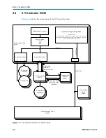
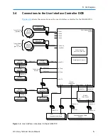
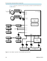
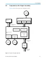

3
XLS Diagrams
XLS Library Technical Service Manual
3-35
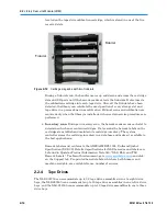
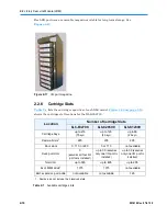
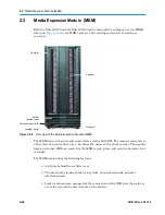
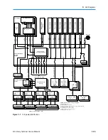
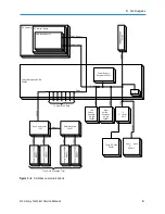
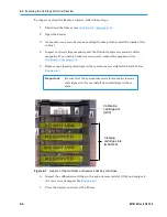
Power Backplane PCBA
520427
-Y
r
204
o
Ri
L
a
on
r
P
021
r I
P
w
upp
S
Ot
er
ve
ys
a
T
iv
a
T
iv
a
T
iv
a
T
iv
PC Chassis
PC Mother Board
+5 SB
Hard
Disk
PC o er
ly
AC Inlet
AC
Power Backplane
PCBA
520427
Power Supply
Controller 520437
+24V
Aux
Connector
LCD Display
To h Dri Ba
Drive Bay Master
521127
Power
Supplies
+5V
+3.3V
+5V
+3.3V
+24V
Drive Bay Slave
521137
eft
C ousel
C troller
PCBA
520957
ght
Carousel
Controller
PCBA
520957
X
Cont ller
5
17
+24V
Drive Carrier
PCBA
520017
Power Supplies
+3.3V
+5V,+12V
Drive Carrier
PCBA
520017
Power Supplies
+3.3V
+5V,+12V
Drive Carrier
PCBA
520017
Power Supplies
+3.3V
+5V,+12V
Drive Carrier
PCBA
520017
Power Supplies
+3.3V
+5V,+12V
Theta-Z CBA
52
7
Use nterface
PCBA
520227
pe Dr e
pe Dr e
pe Dr e
pe Dr e
PCBA’s with Internal Power Supplies:
Battery Module: +5V
Drive Bay Master: +3.3V, +5V
Drive Carrier PCBA: +3.3V; plus +5V, +12V for the Tape Drive
Carousel Controller: +3.3V, +5V
X-Y Controller: +3.3V, +5V, +13.5V
Theta-Z Controller: +3.3V, +5V, +12V
User Interface: +3.3V, +5V
Typical of 8 Drivebays Total
Figure 3-1
XLS power distribution
Summary of Contents for XLS Series
Page 1: ...Technical Service Manual Document No 501610 Rev 07 01 19 XLS Series of Tape Libraries...
Page 14: ...501610 Rev 07 01 19 Part I Before You Begin Notes...
Page 58: ...3 7 Cabling for the Carousel Controller 3 12 501610 Rev 07 01 19 Notes...
Page 70: ...4 5 Inspecting and Cleaning the Gripper and Barcode Reader 4 12 501610 Rev 07 01 19 Notes...
Page 72: ...Part II Using X Link 501610 Rev 07 01 19 Notes...
Page 96: ...Part III Replacing FRUs 501610 Rev 07 01 19 Notes...
Page 136: ...8 8 Bringing a Tape Drive Online 8 14 501610 Rev 07 01 19 Notes...
Page 158: ...9 5 Replacing a Drive Bay with a Cartridge Bay 9 22 501610 Rev 07 01 19 Notes...
Page 172: ...10 3 Replacing a Side Panel 10 14 501610 Rev 07 01 19 Notes...
Page 186: ...11 3 Upgrading a Fixed Port Assembly to an I O Port 11 14 501610 Rev 07 01 19 Notes...
Page 226: ...12 6 Replacing the Y Motor Assembly 12 40 501610 Rev 07 01 19 Notes...
Page 324: ...Part IV Reference 501610 Rev 07 01 19 Notes...
Page 352: ...B 2 Packing the XLS B 14 501610 Rev 07 01 19 Notes...
Page 354: ...C 2 501610 Rev 07 01 19 Notes...


