
7
Replacing Power/PC Bay Components
XLS Library Technical Service Manual
7-
107
5. Install the following components in the replacement bay:
–
Hard drive (see
“Installing
the Hard
Drive”
on page 7-20
–
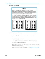
PCI cards (see
“Insta
lling a PCI Card
”
on page 7-18
)
Important:
Be sure to replace the HBAs in the same order as they
were previously installed.
6. Slide the power/PC bay into the frame (see
Section 7.3.2 on page 7-12
).
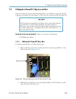
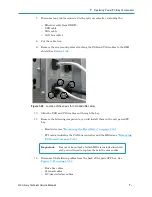
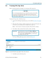
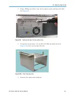
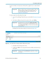
7. Reattach the USB and VGA cables and plates. See
Figure 7-23 on page 7-23
.
8. Reconnect the cables and replace the EMI shield.
9. Reconnect the Ethernet cable.
10. Replace the:
–
Power supplies (see
Section 7.1.2 on page 7-5
)
–
Battery module (see
Section 7.2.2 on page 7-9
)
11. Reconnect the power cord. Make sure the latch clicks and locks the cord in place.
12. Apply power to the library. See
Section 17.2 on page 17-3
.
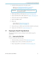
7.7
Replacing the Power/PC Bay Slide Rails
This section describes how to remove and replace the slide rails that support the
power/PC bay.
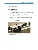
7.7.1
Removing the Slide Rails
To remove the slide rails, follow these steps:
1. Shut down the library and power it off. See
Section 6.2 on page 6-1
.
2. Unplug the power cord. Use your thumb to release the latch.
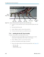
3. Remove the power/PC bay as described in
Section 7.6.1 on page 7-21
.
Summary of Contents for XLS Series
Page 1: ...Technical Service Manual Document No 501610 Rev 07 01 19 XLS Series of Tape Libraries...
Page 14: ...501610 Rev 07 01 19 Part I Before You Begin Notes...
Page 58: ...3 7 Cabling for the Carousel Controller 3 12 501610 Rev 07 01 19 Notes...
Page 70: ...4 5 Inspecting and Cleaning the Gripper and Barcode Reader 4 12 501610 Rev 07 01 19 Notes...
Page 72: ...Part II Using X Link 501610 Rev 07 01 19 Notes...
Page 96: ...Part III Replacing FRUs 501610 Rev 07 01 19 Notes...
Page 136: ...8 8 Bringing a Tape Drive Online 8 14 501610 Rev 07 01 19 Notes...
Page 158: ...9 5 Replacing a Drive Bay with a Cartridge Bay 9 22 501610 Rev 07 01 19 Notes...
Page 172: ...10 3 Replacing a Side Panel 10 14 501610 Rev 07 01 19 Notes...
Page 186: ...11 3 Upgrading a Fixed Port Assembly to an I O Port 11 14 501610 Rev 07 01 19 Notes...
Page 226: ...12 6 Replacing the Y Motor Assembly 12 40 501610 Rev 07 01 19 Notes...
Page 324: ...Part IV Reference 501610 Rev 07 01 19 Notes...
Page 352: ...B 2 Packing the XLS B 14 501610 Rev 07 01 19 Notes...
Page 354: ...C 2 501610 Rev 07 01 19 Notes...


