

15.3
Replacing the Carousel Motor
15-28
501610 Rev. 07-01-19
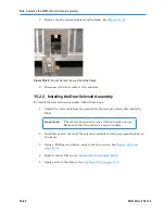
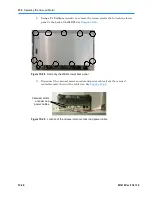
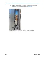
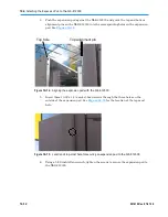
9.
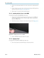
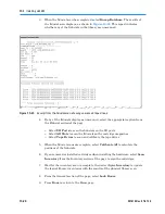
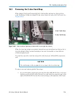
Locate the alignment pin on the carousel motor mount. See
Figure 15-32
.
Carousel
motor mount
alignment pin
Figure 15-32
Location of the alignment pin on the carousel motor mount
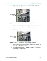
10.
Using pliers, carefully pull up on the pin until it is completely free of the motor
mount and mounting bracket.
11.
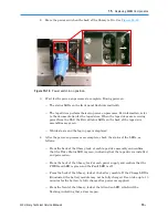
Remove the carousel motor assembly from the back of the MEM.
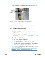
15.3.3 Installing the Carousel Motor
To install the carousel motor, follow these steps:
1.
From the back of the MEM, position the carousel motor assembly into the
mounting bracket.
2.
Align the motor with the mounting bracket, and carefully push down on the
alignment pin to lock the motor into place. See
Figure 15-32 on page 15-28
.
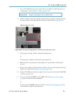
3.
Replace the carousel belt as follows:
a.
Place the belt around the carousel pulley.
b.
Slide the belt around the gear assembly under the carousel.
c.
Push the carousel motor toward the left pillar on the MEM frame and
confirm that the belt does not slip off the gear or the pulley.
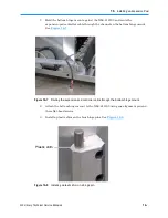
4.
Use a 3/16-inch Allen wrench to replace the belt-tensioning screw, shown in
Figure 15-31 on page 15-27
.
Important:
Keep the belt-tensioning screw slightly loose.
Summary of Contents for XLS Series
Page 1: ...Technical Service Manual Document No 501610 Rev 07 01 19 XLS Series of Tape Libraries...
Page 14: ...501610 Rev 07 01 19 Part I Before You Begin Notes...
Page 58: ...3 7 Cabling for the Carousel Controller 3 12 501610 Rev 07 01 19 Notes...
Page 70: ...4 5 Inspecting and Cleaning the Gripper and Barcode Reader 4 12 501610 Rev 07 01 19 Notes...
Page 72: ...Part II Using X Link 501610 Rev 07 01 19 Notes...
Page 96: ...Part III Replacing FRUs 501610 Rev 07 01 19 Notes...
Page 136: ...8 8 Bringing a Tape Drive Online 8 14 501610 Rev 07 01 19 Notes...
Page 158: ...9 5 Replacing a Drive Bay with a Cartridge Bay 9 22 501610 Rev 07 01 19 Notes...
Page 172: ...10 3 Replacing a Side Panel 10 14 501610 Rev 07 01 19 Notes...
Page 186: ...11 3 Upgrading a Fixed Port Assembly to an I O Port 11 14 501610 Rev 07 01 19 Notes...
Page 226: ...12 6 Replacing the Y Motor Assembly 12 40 501610 Rev 07 01 19 Notes...
Page 324: ...Part IV Reference 501610 Rev 07 01 19 Notes...
Page 352: ...B 2 Packing the XLS B 14 501610 Rev 07 01 19 Notes...
Page 354: ...C 2 501610 Rev 07 01 19 Notes...


