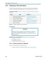


14.5
Replacing Light Curtain Sensors
14-10
501610 Rev. 07-01-19
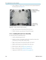
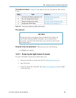
4.
Replace the front panel. See
Section 10.2 on page 10-7
.
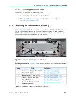
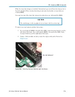
5.
Refer to
Section 17.4 on page 17-8
to power on the library and scan the
fiducials and inventory.
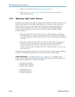
14.5
Replacing Light Curtain Sensors
The light curtain, also known as the Inventor Sentry, consists of a number of emitter and
detector pairs installed in the LRM and MEM cabinets. The emitters, mounted on the
bottom of the cabinet, project small beams of light up to the corresponding detectors,
mounted at the top of the cabinet. The curtain of light formed by the emitters and
detectors allows the XLS to precisely monitor all areas within the LRM and MEM
cabinets, as follows:
•
The beams of light at the rear of the cabinet can detect whether a cartridge is
protruding from a slot. If the door(s) are closed and one of these beams of light is
broken, the XLS prevents the handler from moving to avoid hitting a protruding
cartridge.
•
The beams of light curtain at the front of the cabinet can detect when someone
reaches into the cabinet. If a door is open and one of these beams of light is
broken, the XLS detects and logs a potential inventory violation and
automatically scans the cartridges and drives in the affected area as soon as all
doors are closed.
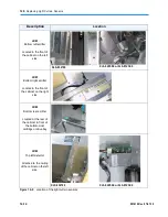
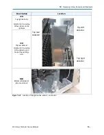
The light curtain assembly consists of a series of printed circuit board assemblies (PCBAs)
and cables. The PCBAs are attached to the cabinet with sheet-metal brackets.
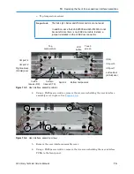
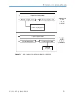
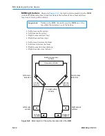
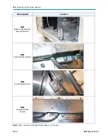
LRM Light Curtain:
As shown in
Figure 14-7 on page 14-11
, the light curtain
assembly for the LRM includes PCBAs and cables in three locations at the bottom of the
cabinet and three locations at the top of the cabinet:
•
Bottom left (emitters)
•
Bottom right (emitters)
•
Bottom rear (emitters)
•
Top left (detectors)
•
Top right (detectors)
•
Top rear (detectors)
Summary of Contents for XLS Series
Page 1: ...Technical Service Manual Document No 501610 Rev 07 01 19 XLS Series of Tape Libraries...
Page 14: ...501610 Rev 07 01 19 Part I Before You Begin Notes...
Page 58: ...3 7 Cabling for the Carousel Controller 3 12 501610 Rev 07 01 19 Notes...
Page 70: ...4 5 Inspecting and Cleaning the Gripper and Barcode Reader 4 12 501610 Rev 07 01 19 Notes...
Page 72: ...Part II Using X Link 501610 Rev 07 01 19 Notes...
Page 96: ...Part III Replacing FRUs 501610 Rev 07 01 19 Notes...
Page 136: ...8 8 Bringing a Tape Drive Online 8 14 501610 Rev 07 01 19 Notes...
Page 158: ...9 5 Replacing a Drive Bay with a Cartridge Bay 9 22 501610 Rev 07 01 19 Notes...
Page 172: ...10 3 Replacing a Side Panel 10 14 501610 Rev 07 01 19 Notes...
Page 186: ...11 3 Upgrading a Fixed Port Assembly to an I O Port 11 14 501610 Rev 07 01 19 Notes...
Page 226: ...12 6 Replacing the Y Motor Assembly 12 40 501610 Rev 07 01 19 Notes...
Page 324: ...Part IV Reference 501610 Rev 07 01 19 Notes...
Page 352: ...B 2 Packing the XLS B 14 501610 Rev 07 01 19 Notes...
Page 354: ...C 2 501610 Rev 07 01 19 Notes...


