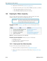


13.2
Replacing the User Interface Assembly
13-8
501610 Rev. 07-01-19
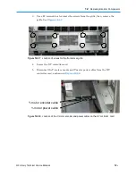
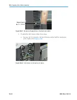
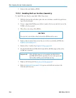
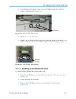
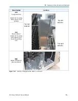
7.
Remove the user interface PCBA.
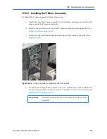
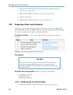
13.2.2 Installing the User Interface Assembly
To install the user interface assembly, follow these steps:
1.
With the front panel on the floor, place the user interface assembly in position on
top of the front panel.
2.
Using a magnetized Phillips screwdriver, replace the two screws that secure the
PCBA to the front panel.
3.
Place the cover on top of the PCBA.
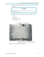
CAUTION
Be sure not to pinch the cables between the PCBA and the cover.
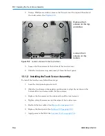
4.
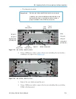
Replace the six screws that secure the cover to the user interface PCBA. See
Figure 13-6 on page 13-7
.
5.
Reattach the 14 cables. See
Figure 13-5 on page 13-7
.
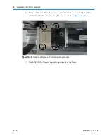
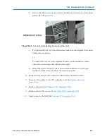
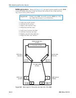
6.
For the XLS-820500 and XLS-812300, install the LCAB jumper cable on the
LCAB door connector.
Important:
If the LCAB jumper is not installed, the XLS-820500
and XLS-812300 will respond as if a door were open and
the handler will be prevented from moving.
7.
Replace the front panel. See
Section 10.2 on page 10-7
.
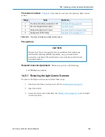
8.
Refer to
Section 17.4 on page 17-8
to power on the library and scan the
fiducials and inventory.
Summary of Contents for XLS Series
Page 1: ...Technical Service Manual Document No 501610 Rev 07 01 19 XLS Series of Tape Libraries...
Page 14: ...501610 Rev 07 01 19 Part I Before You Begin Notes...
Page 58: ...3 7 Cabling for the Carousel Controller 3 12 501610 Rev 07 01 19 Notes...
Page 70: ...4 5 Inspecting and Cleaning the Gripper and Barcode Reader 4 12 501610 Rev 07 01 19 Notes...
Page 72: ...Part II Using X Link 501610 Rev 07 01 19 Notes...
Page 96: ...Part III Replacing FRUs 501610 Rev 07 01 19 Notes...
Page 136: ...8 8 Bringing a Tape Drive Online 8 14 501610 Rev 07 01 19 Notes...
Page 158: ...9 5 Replacing a Drive Bay with a Cartridge Bay 9 22 501610 Rev 07 01 19 Notes...
Page 172: ...10 3 Replacing a Side Panel 10 14 501610 Rev 07 01 19 Notes...
Page 186: ...11 3 Upgrading a Fixed Port Assembly to an I O Port 11 14 501610 Rev 07 01 19 Notes...
Page 226: ...12 6 Replacing the Y Motor Assembly 12 40 501610 Rev 07 01 19 Notes...
Page 324: ...Part IV Reference 501610 Rev 07 01 19 Notes...
Page 352: ...B 2 Packing the XLS B 14 501610 Rev 07 01 19 Notes...
Page 354: ...C 2 501610 Rev 07 01 19 Notes...


