
2.2
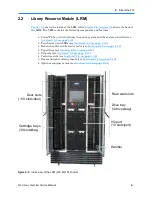
Library Resource Module (LRM)
2-12
501610 Rev. 07-01-19
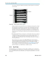
carousel of an attached MEM. The handler is controlled by the medium changer interface
and shared by all host software applications on a first-come, first-served basis.
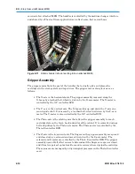
Figure 2-11
Robotic handler (shown reaching into an attached MEM)
Gripper Assembly
The gripper assembly is the part of the handler that actually picks and places the
cartridges in the storage slots and tape drives. The gripper moves along four axes, as
follows:
•
The
X-axis
is the horizontal axis. The gripper assembly is moved along the
X-beam by a toothed belt, which is driven by the X-axis motor. The X-motor is
controlled by the X-Y controller DCB.
•
The
Y-axis
is the vertical axis. The X-beam rides up and down the Y-axis on a
round guide shaft. It is moved by a toothed belt, which is driven by the Y-axis
motor. The Y-motor is also controlled by the X-Y controller DCB.
•
The
Theta-axis
is the rotating axis that allows the gripper assembly to reach
cartridge slots on the front, back, and sides of the cabinet. It is controlled using a
belt and pulleys by the Theta-axis motor. The Theta-motor is controlled by the
Theta-Z controller DCB.
•
The
Z-axis
is the in-and-out axis. The fingers on the gripper assembly are opened
and closed using a solenoid and moved in and out by the Z-axis motor. The
solenoid and Z-motor are controlled by the Theta-Z controller DCB. The gripper
assembly uses a Hall effect sensor to determine if the fingers are open or closed,
and it has two pairs of optical emitters and receivers where it grips the cartridge.
These sensors are managed by a digital signal processor on the Theta-Z controller
card.
Summary of Contents for XLS Series
Page 1: ...Technical Service Manual Document No 501610 Rev 07 01 19 XLS Series of Tape Libraries...
Page 14: ...501610 Rev 07 01 19 Part I Before You Begin Notes...
Page 58: ...3 7 Cabling for the Carousel Controller 3 12 501610 Rev 07 01 19 Notes...
Page 70: ...4 5 Inspecting and Cleaning the Gripper and Barcode Reader 4 12 501610 Rev 07 01 19 Notes...
Page 72: ...Part II Using X Link 501610 Rev 07 01 19 Notes...
Page 96: ...Part III Replacing FRUs 501610 Rev 07 01 19 Notes...
Page 136: ...8 8 Bringing a Tape Drive Online 8 14 501610 Rev 07 01 19 Notes...
Page 158: ...9 5 Replacing a Drive Bay with a Cartridge Bay 9 22 501610 Rev 07 01 19 Notes...
Page 172: ...10 3 Replacing a Side Panel 10 14 501610 Rev 07 01 19 Notes...
Page 186: ...11 3 Upgrading a Fixed Port Assembly to an I O Port 11 14 501610 Rev 07 01 19 Notes...
Page 226: ...12 6 Replacing the Y Motor Assembly 12 40 501610 Rev 07 01 19 Notes...
Page 324: ...Part IV Reference 501610 Rev 07 01 19 Notes...
Page 352: ...B 2 Packing the XLS B 14 501610 Rev 07 01 19 Notes...
Page 354: ...C 2 501610 Rev 07 01 19 Notes...


