

15
Replacing MEM Components
XLS Library Technical Service Manual
15-
247
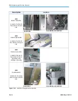
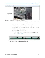
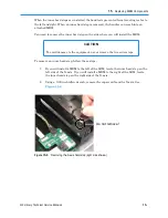
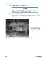
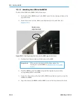
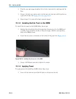
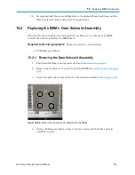
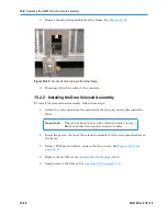
2. Locate the two socket-head cap screws on each bracket. See
Figure 15-8
.
1
4
3
2
Left side of MEM
Figure 15-8
Location of screws on the carousel shipping locks
Right side of MEM
–
The screws on the left side of the brackets (screws 1 and 2 in
Figure 15-8
)
have a stationary PEM nut and function to raise and lower the carousel.
–
The screws on the right side of the bracket (screws 3 and 4 in
Figure 15-8
)
are shipping locks and function to keep the carousel from rotating.
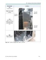
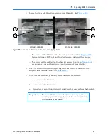
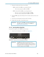
3. Use a 5/16-inch Allen wrench (right-angled, if possible) to remove the two
shipping locks (screws 3 and 4 in
Figure 15-8
).
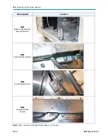
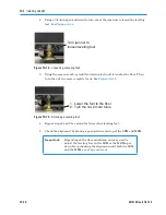
4. Using the same wrench, gradually lower the carousel as follows:
a. Loosen screw 1 a few turns.
b. Loosen screw 2 a few turns.
c. Repeat steps a and b until screws 1 and 2 can be removed from the brackets.
Important:
To ensure that the carousel is lowered evenly and to
avoid equipment damage, be sure to loosen screws 1 and
2 in tandem as described.
Summary of Contents for XLS Series
Page 1: ...Technical Service Manual Document No 501610 Rev 07 01 19 XLS Series of Tape Libraries...
Page 14: ...501610 Rev 07 01 19 Part I Before You Begin Notes...
Page 58: ...3 7 Cabling for the Carousel Controller 3 12 501610 Rev 07 01 19 Notes...
Page 70: ...4 5 Inspecting and Cleaning the Gripper and Barcode Reader 4 12 501610 Rev 07 01 19 Notes...
Page 72: ...Part II Using X Link 501610 Rev 07 01 19 Notes...
Page 96: ...Part III Replacing FRUs 501610 Rev 07 01 19 Notes...
Page 136: ...8 8 Bringing a Tape Drive Online 8 14 501610 Rev 07 01 19 Notes...
Page 158: ...9 5 Replacing a Drive Bay with a Cartridge Bay 9 22 501610 Rev 07 01 19 Notes...
Page 172: ...10 3 Replacing a Side Panel 10 14 501610 Rev 07 01 19 Notes...
Page 186: ...11 3 Upgrading a Fixed Port Assembly to an I O Port 11 14 501610 Rev 07 01 19 Notes...
Page 226: ...12 6 Replacing the Y Motor Assembly 12 40 501610 Rev 07 01 19 Notes...
Page 324: ...Part IV Reference 501610 Rev 07 01 19 Notes...
Page 352: ...B 2 Packing the XLS B 14 501610 Rev 07 01 19 Notes...
Page 354: ...C 2 501610 Rev 07 01 19 Notes...


