
15
Replacing MEM Components
XLS Library Technical Service Manual
15-
263
15.3
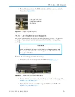
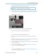
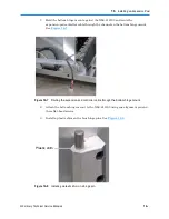
Replacing the Carousel Motor
The carousel motor, located at the back of the MEM, controls the rotation of the carousel.
Important:
The XLS can remain powered on when you replace the
carousel motor.
Procedure overview:
Table 15-2
provides an overview of replacing the carousel
motor.
Step
Task
Refer to...
1
Power off the carousel controller
Section 15.3.1 on page 15-23
2
Remove the carousel motor
Section 15.3.2 on page 15-25
3
Replace the carousel motor
Section 15.3.3 on page 15-28
4
Power on the carousel controller
Section 15.3.4 on page 15-30
Table 15-2
Overview of replacing the carousel motor
Required tools and equipment:
Make sure you have the following:
•
#2 Phillips screwdriver
•
3/16-inch Allen wrench
•
Standard pliers
•
Cable tie cutters
•
Replacement cable ties
•
Small metric ruler or calipers
•
1/4-inch Allen wrench (if the MEM is to the left of the LRM)
15.3.1 Powering Off the Carousel Controller
Before removing the carousel motor, you need to power off the carousel controller.
Powering off the controller shuts down the carousel motor, the door-lock solenoids in the
MEM, and the MEM light curtain sensors.
To power off the carousel controller, follow these steps:
1. Make sure that no backup operations are in process, then shut down the
applications. Refer to the documentation for the software applications.
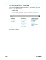
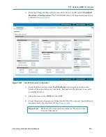
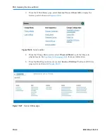
2. Log in to X-Link.
Summary of Contents for XLS Series
Page 1: ...Technical Service Manual Document No 501610 Rev 07 01 19 XLS Series of Tape Libraries...
Page 14: ...501610 Rev 07 01 19 Part I Before You Begin Notes...
Page 58: ...3 7 Cabling for the Carousel Controller 3 12 501610 Rev 07 01 19 Notes...
Page 70: ...4 5 Inspecting and Cleaning the Gripper and Barcode Reader 4 12 501610 Rev 07 01 19 Notes...
Page 72: ...Part II Using X Link 501610 Rev 07 01 19 Notes...
Page 96: ...Part III Replacing FRUs 501610 Rev 07 01 19 Notes...
Page 136: ...8 8 Bringing a Tape Drive Online 8 14 501610 Rev 07 01 19 Notes...
Page 158: ...9 5 Replacing a Drive Bay with a Cartridge Bay 9 22 501610 Rev 07 01 19 Notes...
Page 172: ...10 3 Replacing a Side Panel 10 14 501610 Rev 07 01 19 Notes...
Page 186: ...11 3 Upgrading a Fixed Port Assembly to an I O Port 11 14 501610 Rev 07 01 19 Notes...
Page 226: ...12 6 Replacing the Y Motor Assembly 12 40 501610 Rev 07 01 19 Notes...
Page 324: ...Part IV Reference 501610 Rev 07 01 19 Notes...
Page 352: ...B 2 Packing the XLS B 14 501610 Rev 07 01 19 Notes...
Page 354: ...C 2 501610 Rev 07 01 19 Notes...


