


12.1
Replacing the Gripper Assembly
12-10
501610 Rev. 07-01-19
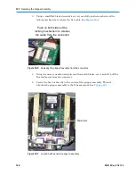
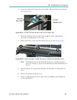
3.
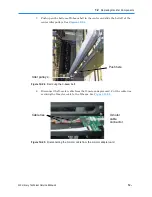
Move the X-beam by hand until the gripper assembly is just under the gripper
alignment cartridge.
Important:
Make sure the alignment cartridge aligns with the
gripper assembly guide rod. The alignment cartridge
should be flush with the gripper assembly and the
cartridge slot.
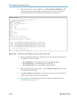
4.
Select
Get Robot Status
. X-Link displays information about the
robot’
s position.
5.
Write down the values for Left Theta Position
(“TPOS”)
and X Position
(“'XPOS”
).
6.
Move the X-beam down by hand so that it is not blocking the gripper alignment
cartridge.
7.
Remove the gripper alignment cartridge.
8.
Align the gripper assembly with the right back wall as described in
Section 12.1.5
.
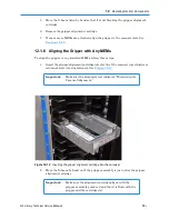
12.1.5 Aligning the Gripper Assembly with the Right Back Wall
To align the gripper assembly with the right back wall, follow these steps:
1.
Insert the gripper alignment cartridge into the right column of the back wall as
follows:
–
XLS-832700:
Insert the cartridge into slot
H36
–
XLS-820500:
Insert the cartridge in the slot
G36
–
XLS-812300:
Insert the cartridge into slot
G36
Important:
Make sure the alignment cartridge indicates
“This
side
up for Theta Alignment.
”
2.
Move the X-beam by hand until the gripper assembly is just under the gripper
alignment cartridge.
Important:
Make sure the alignment cartridge aligns with the
gripper assembly guide rod. The alignment cartridge
should be flush with the gripper assembly and the
cartridge slot.
3.
Select
Get Robot Status
. X-Link displays information about the
robot’
s position.
4.
Write down the values for Right Theta Position
(“TPOS”
) and X Position
(“'X
P
OS”).
Summary of Contents for XLS Series
Page 1: ...Technical Service Manual Document No 501610 Rev 07 01 19 XLS Series of Tape Libraries...
Page 14: ...501610 Rev 07 01 19 Part I Before You Begin Notes...
Page 58: ...3 7 Cabling for the Carousel Controller 3 12 501610 Rev 07 01 19 Notes...
Page 70: ...4 5 Inspecting and Cleaning the Gripper and Barcode Reader 4 12 501610 Rev 07 01 19 Notes...
Page 72: ...Part II Using X Link 501610 Rev 07 01 19 Notes...
Page 96: ...Part III Replacing FRUs 501610 Rev 07 01 19 Notes...
Page 136: ...8 8 Bringing a Tape Drive Online 8 14 501610 Rev 07 01 19 Notes...
Page 158: ...9 5 Replacing a Drive Bay with a Cartridge Bay 9 22 501610 Rev 07 01 19 Notes...
Page 172: ...10 3 Replacing a Side Panel 10 14 501610 Rev 07 01 19 Notes...
Page 186: ...11 3 Upgrading a Fixed Port Assembly to an I O Port 11 14 501610 Rev 07 01 19 Notes...
Page 226: ...12 6 Replacing the Y Motor Assembly 12 40 501610 Rev 07 01 19 Notes...
Page 324: ...Part IV Reference 501610 Rev 07 01 19 Notes...
Page 352: ...B 2 Packing the XLS B 14 501610 Rev 07 01 19 Notes...
Page 354: ...C 2 501610 Rev 07 01 19 Notes...


