10
Cut any excess tube that protrudes into
either cavity.
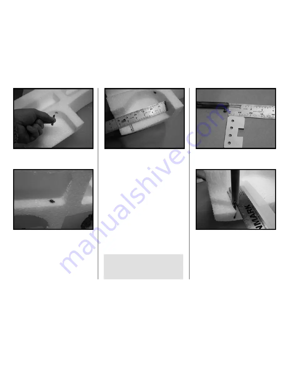
7. Before joining the fuse halves you
will be making the cavities for the nose
wheel retract’s rear supports as it is
easier to do this now. Mark a line on
each side of the nose wheel cavity 5”
from the back of the cavity.
Mark another line 1/4” aft of the first line.
You will be cutting a channel about one
inch deep within the lines to
accommodate the rear rail support. The
easiest way to do this is to burn the
foam with a brass tube and soldering
iron. You could also use a long X-acto
knife, route with a dremel, or heat a
tube/wire with a torch/lighter. In the
photo below we inserted a 1/8” brass
tube into a soldering iron (you want the
tube or wire to be less than 1/4” as the
foam will melt easily).
The rear rail support is the first of the
laminated 1/8” plywood pieces you will
be working with. If you have not already
done so, laminate two pieces together to
form a piece ¼” thick.
Tip: Inserting a 1/8” dia. music wire into
a scrap wood block provides a stable
alignment tool for the lamination
process. Make two. Use a clamp to
squeeze the 1/8” parts together.
Taping a metal ruler to the wheel cavity
will help guide the soldering iron.
Once you make the initial cut in the side,
you will need to remove more material
from the roof of the cavity to
accommodate the length of the ply
support. The slightly curved end of the
support matches the bottom contour of
the fuse.
Summary of Contents for T-34C TURBO MENTOR
Page 190: ...191 This Page Intentionally Left Blank ...
Page 191: ...192 Fin Rudder Template ...
Page 192: ...193 This Page Intentionally Left Blank ...
Page 193: ...194 ...
Page 194: ...195 This Page Intentionally Left Blank ...
Page 195: ...196 Laser Cut Parts Diagram ...


