


24 . Clarus 590 GC User’s Guide
Touch Screen
The main display area on the touch screen are referred to as screens. You use various screens to set up
your Clarus GC to perform the analyses. These screens contain:
•
Entry fields
which allow you to make entries,
•
Buttons
that you touch to start or stop actions or to display a dialog,
•
Option Buttons
that you select drop down menu options from a list,
•
Boxes
that you use to switch functions on or off and
•
Radio Button
that allow you to choose one of two or more options.
The Clarus GC is controlled by a collection of operating parameters called the Active Method. You can
prepare and save up to five methods and make any one of them the Active Method. However, the fifth
method is reserved for TotalChrom and may be overwritten.
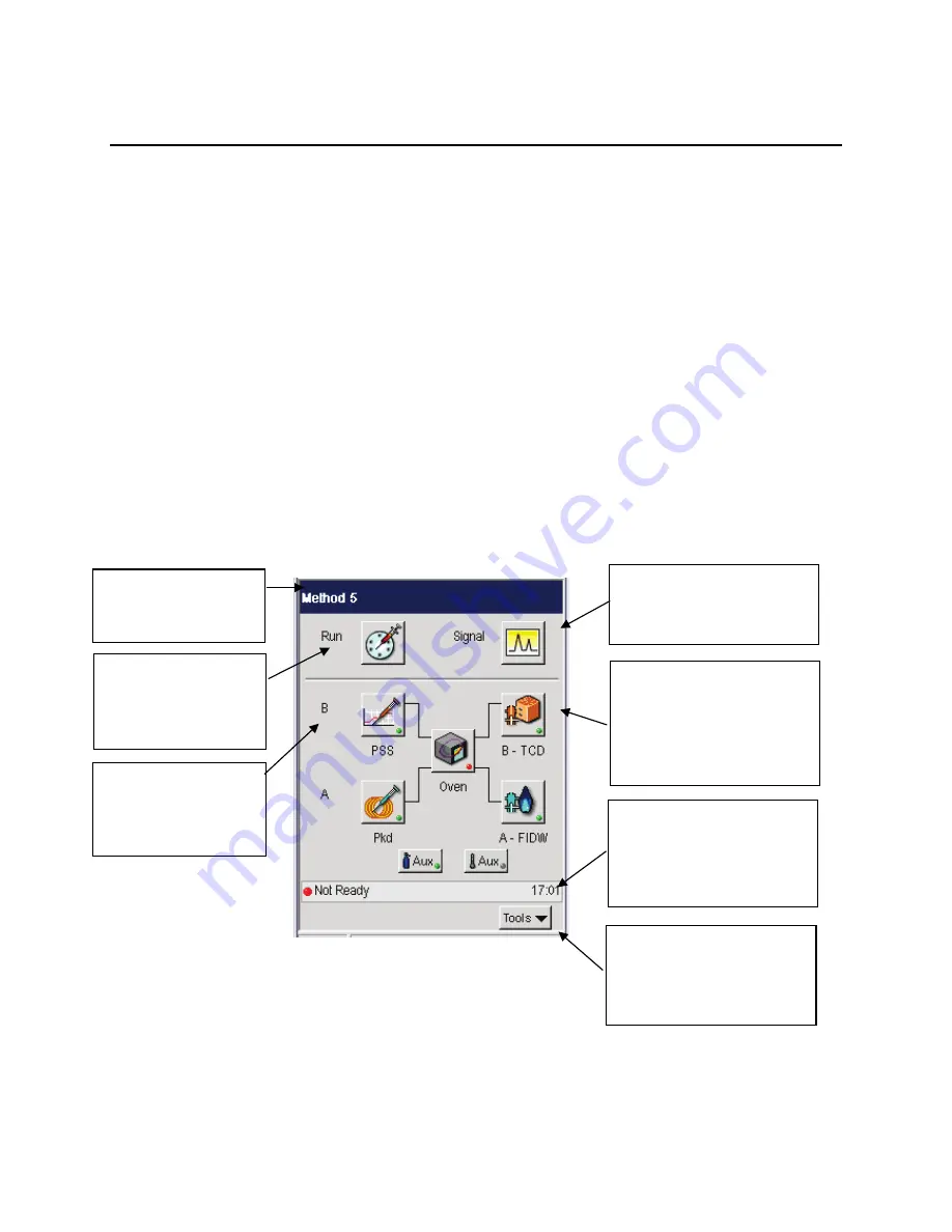
The following Status screen shows the different sections of the user interface.
The Status Screen displays icons that provide quick access to major areas of the system. The injector and
detector buttons show graphic representations of the devices for each channel. If a heated auxiliary zone
is configured, the Aux button with a thermometer appears active on the bottom of the screen. The Aux
zone button with the carrier gas icon indicates the PPC carrier gas zone is active. The icon buttons that
represent the heated zones (injectors, detectors, oven, and Aux if configured) include a light to indicate
the ready/not ready status. A red blinking light indicates not ready and a steady green light indicates
ready status.
Click here to view the Signal.
If a method is not running
the screen will display a
baseline.
The Title bar displays
the name of the active
method.
The Run button
provides access to the
Autosampler and
Manual Inject settings.
Channel B appears on
top of Channel A to
emulate the order on
top of the GC.
The Icon buttons provide
quick access to all configured
areas of the instrument. An
indicator light shows the
ready/not ready status of
each heated zone.
The status bar displays the
overall ready/not ready status
as well as text messages and
the real time clock/date
display.
The bottom bar displays the
Tools pop up menu. When
the system is running the
Stop button also appears.
Summary of Contents for CLARUS 590 GC
Page 1: ...CLARUS 590 GC User s Guide GAS CHROMATOGRAPHY ...
Page 9: ...About This Manual 9 Flame Ionization Detector FID 270 TCD 273 Autosampler 277 Index 279 ...
Page 10: ...10 Clarus 590 GC User s Guide ...
Page 11: ...1 Introduction ...
Page 12: ...12 Clarus 590 GC User s Guide ...
Page 21: ...2 Touch Screen Navigation ...
Page 22: ...22 Clarus 590 GC User s Guide ...
Page 48: ...48 Clarus 590 GC User s Guide PPC Active Method Configuration Screen Manual Pneumatics ...
Page 50: ...50 Clarus 590 GC User s Guide PPC Active Method Configuration Screen Manual Pneumatics ...
Page 59: ...3 Using the Active Method ...
Page 60: ...60 Clarus 590 GC User s Guide ...
Page 109: ...4 Setting Up the Detectors ...
Page 110: ...110 Clarus 590 GC User s Guide ...
Page 197: ...5 Using the Method Editor ...
Page 198: ...198 Clarus 590 GC User s Guide ...
Page 207: ...6 Using the Tools Menu ...
Page 208: ...208 Clarus 590 GC User s Guide ...
Page 224: ...224 Clarus 590 GC User s Guide ECD PID NPD FPD ...
Page 225: ...Detectors 225 Output Configured ...
Page 262: ...262 Clarus 590 GC User s Guide ...
Page 263: ...7 Setting up a Typical Analysis ...
Page 264: ...264 Clarus 590 GC User s Guide ...
Page 279: ...Index ...
Page 280: ...280 Clarus 590 GC User s Guide ...


