170
6-2-5 Setting of code reader linkage functions
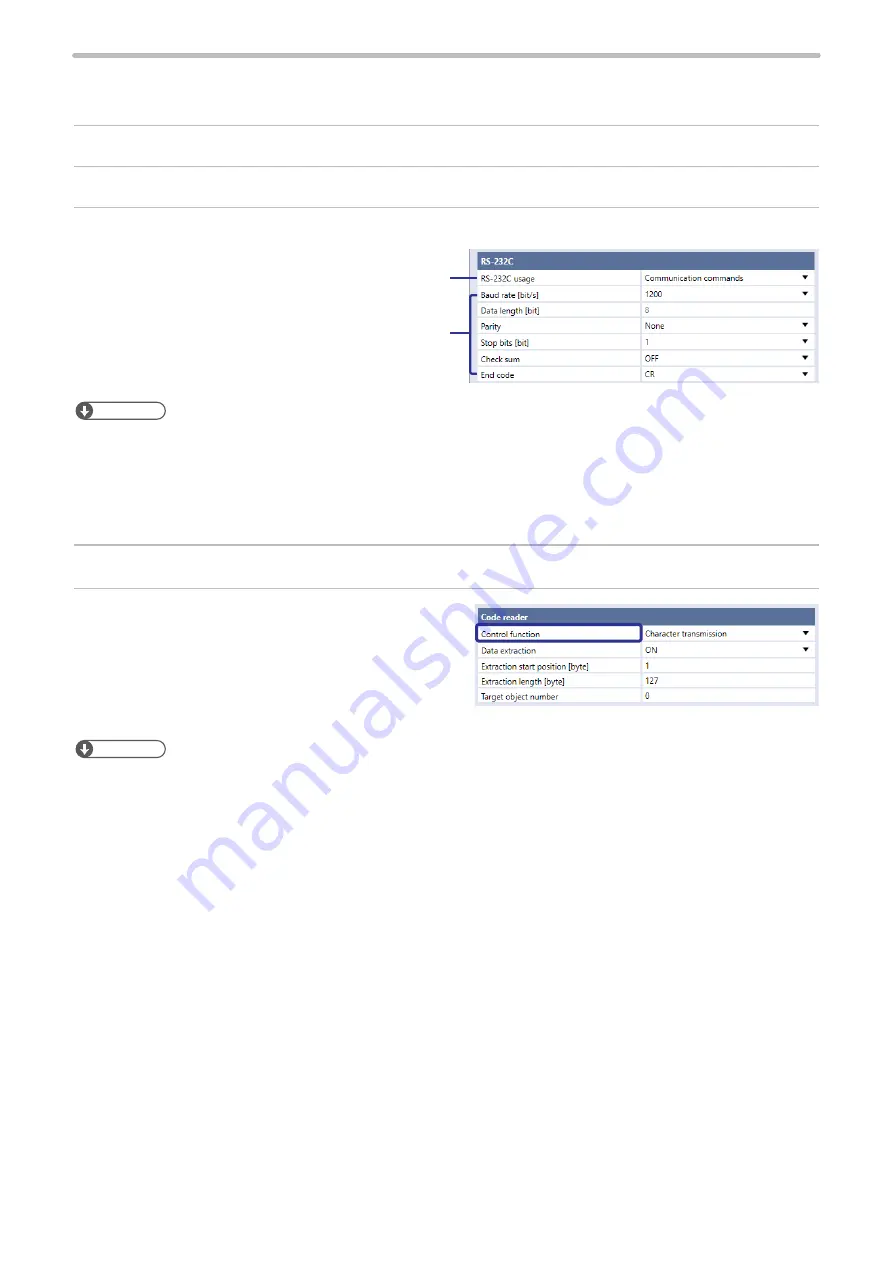
For use of the code reader linkage function, set the following items in the Laser Marker NAVI smart system settings screen.
1.
Establish an online connection between your PC and the laser marking system.
2.
Go to the “System settings” screen and select “Communication” tab.
3.
Select the usage and communication settings of RS-232C.
Specify these values according to
communication settings of the code
reader to connect.
Set “Code reader” to the RS-232C
usage.
ンㄆㄇㄆㄓㄆㄏㄆ
• For the code reader linkage function, the following items of communication settings are fixed values. Align the code
reader side settings with this setting.
• Start code: None
• Checksum: OFF
• End code: CR
4.
In the “System settings” screen, select the “Linked device” tab.
5.
Under “Code reader”, set “Control function”. Select
types of data to be controlled by the code reader linkage
function.
• File switching by name
• File switching by number
• Character transmission
ンㄆㄇㄆㄓㄆㄏㄆ
• File switching and character data transmission cannot be used at the same time.
ME-LPRH-SM-3
Summary of Contents for LP-RH Series
Page 19: ...1 Product Overview ME LPRH SM 3...
Page 42: ...2 Laser Marker Installation ME LPRH SM 3...
Page 68: ...3 Operation Method ME LPRH SM 3...
Page 90: ...4 External Control Using I O ME LPRH SM 3...
Page 138: ...5 External Control by Communication Commands ME LPRH SM 3...
Page 147: ...6 Link Control with External Devices ME LPRH SM 3...
Page 172: ...7 Maintenance ME LPRH SM 3...
Page 201: ...Troubleshooting ME LPRH SM 3...
Page 236: ...Index ME LPRH SM 3...
Page 239: ......


