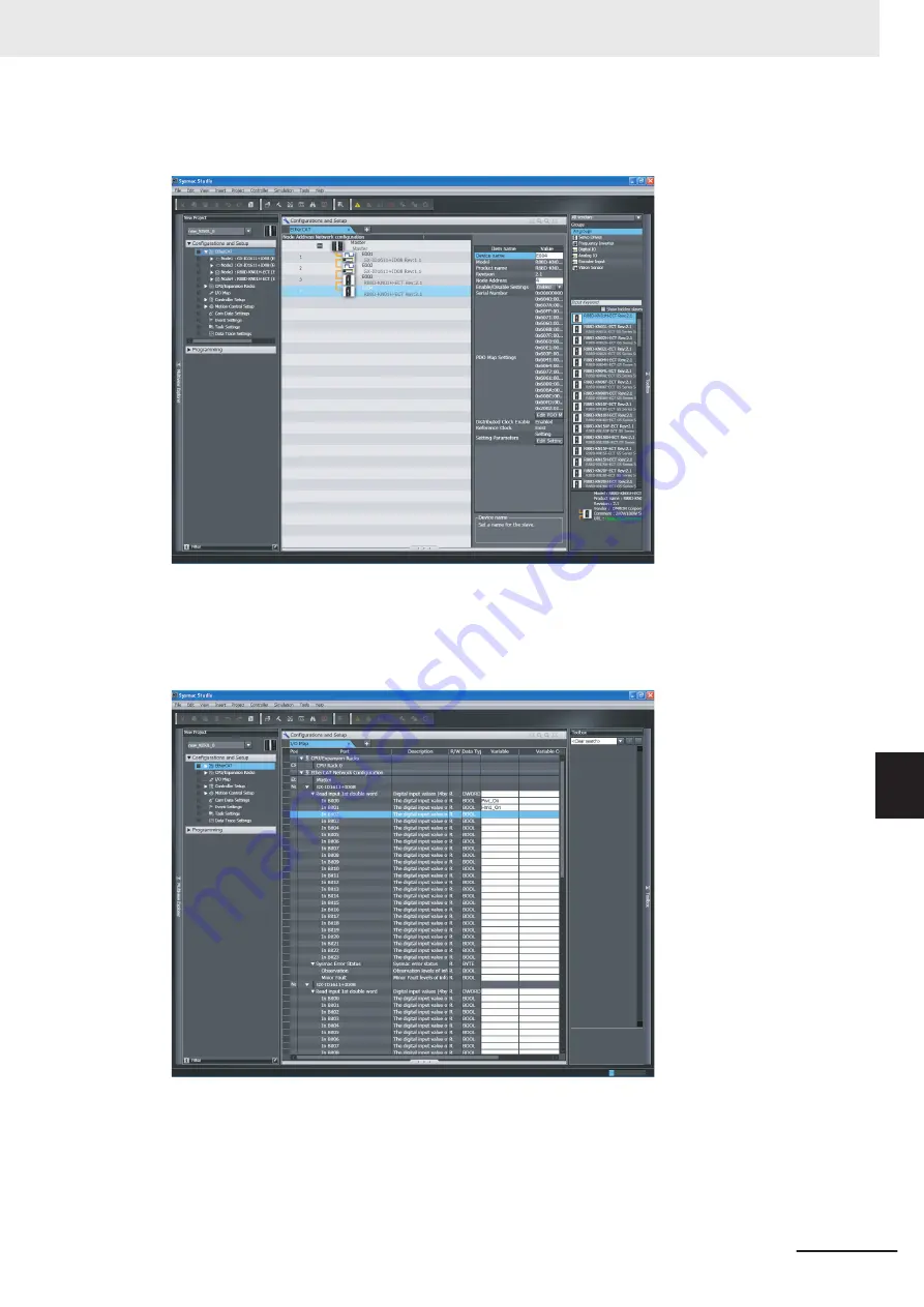
Creating the EtherCAT Network Configuration
Use the EtherCAT Configuration Editor to create the slave configuration.
In this example, digital I/O slaves are set to node addresses 1 and 2 and Servo Drives are set to
node addresses 3 and 4.
Assigning Device Variables to Digital I/O Slaves (Node Addresses 1 and 2)
Use the I/O Map to assign device variables to the I/O ports of the slaves.
In this example,
Pwr_On
is assigned to bit 0 of slave 1 and
Hm1_On
is assigned to bit 1 of slave 1.
Axis Settings for the Servo Drives (Node Addresses 3 and 4)
Add an axis to the Motion Control Setup and then assign the Servo Drive with node address 3 to
the axis to set the axis.
8 Example of Operations for EtherCAT Communications
8-3
NJ/NX-series CPU Unit Built-in EtherCAT Port User's Manual (W505)
8-1
Example of Operations for EtherCA
T Communications
8
8-1-3
Setting the EtherCA
T Network Configuration
Summary of Contents for NJ101-10 Series
Page 10: ...Manual Structure 8 NJ NX series CPU Unit Built in EtherCAT Port User s Manual W505...
Page 80: ...3 EtherCAT Communications 3 12 NJ NX series CPU Unit Built in EtherCAT Port User s Manual W505...
Page 236: ...9 Troubleshooting 9 38 NJ NX series CPU Unit Built in EtherCAT Port User s Manual W505...
Page 274: ...Appendices A 38 NJ NX series CPU Unit Built in EtherCAT Port User s Manual W505...
Page 275: ...I Index I 1 NJ NX series CPU Unit Built in EtherCAT Port User s Manual W505 I...
Page 279: ......


