background image

H186-E1-05

1

2

3

5

6

7

A

I

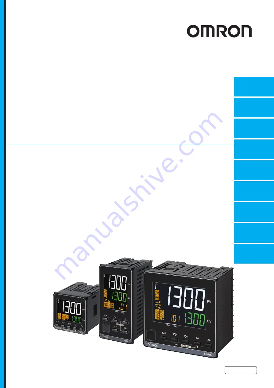
Digital Temperature Controllers 
Programmable Type

Communications Manual

E5

@

C-T

Communications

Data for CompoWay/F

CompoWay/F Commu-

nications Procedures

Communications

Methods

Communications

Data for Modbus

Programless 

Communications

Component 

Communications

Modbus Communica-

tions Procedure

Appendices

Index

4

Summary of Contents for E5CC-T

Page 1: ...ble Type Communications Manual E5 C T Communications Data for CompoWay F CompoWay F Commu nications Procedures Communications Methods Communications Data for Modbus Programless Communications Componen...

Page 2: ......

Page 3: ...n may be reproduced stored in a retrieval system or transmitted in any form or by any means mechanical electronic photocopying recording or otherwise without the prior written permission of OMRON No p...

Page 4: ...to the purchase price of the non complying Product provided that in no event shall Omron be responsible for warranty repair indemnity or any other claims or expenses regarding the Products unless Omro...

Page 5: ...on Companies shall not be responsible for the user s programming of a programmable Product or any consequence thereof Data presented in Omron Company websites catalogs and other materials is provided...

Page 6: ...p erty damage Precautions for Safe Use Supplementary comments on what to do or avoid doing to use the product safely Precautions for Correct Use Supplementary comments on what to do or avoid doing to...

Page 7: ...ion may occasionally occur Do not use the product where subject to flammable or explosive gas Fire may occasionally occur Do not allow dirt or other foreign objects to enter a Setup Tool port or betwe...

Page 8: ...that they are suitable for the system being controlled If they are not suitable unexpected operation may occasionally result in property damage or accidents A malfunction in the Digital Controller may...

Page 9: ...th is 6 to 8 mm Up to two wires of the same size and type or two crimped terminals can be inserted into a single terminal Do not wire the terminals that are not used To avoid inductive noise keep the...

Page 10: ...Digital Controller apart for disposal Sharp parts inside the Digital Controller may cause injury Do not connect cables to both the front panel Setup Tool port and the top panel Setup Tool port at the...

Page 11: ...rammable Type Communications Manual H186 Trademarks MELSEC and GX Works are trademarks of the Mitsubishi Electric Corporation Other company names and product names in this document are the trademarks...

Page 12: ...s Manual H186 Versions Check the version on the nameplate on the E5 C T Controller or on the label on the packing box If the version is not given the version of the E5 C T Controller is version 1 0 Pr...

Page 13: ...to notes in table Added RS 485 for port 2 of CP series CPU Units Page 6 8 Changed numbers from 15 to 18 in table Pages 6 31 6 32 6 48 and 6 49 Changed screen capture at bottom of page Page 7 2 Added n...

Page 14: ...Revision History 12 E5 C T Digital Temperature Controllers Programmable Type Communications Manual H186...

Page 15: ...cedure Communications Data for Modbus Programless Communications Component Communications A Appendices I Index A I Sections in This Manual Descriptions in this manual are separated by the communicatio...

Page 16: ...Transmission Procedure 1 3 1 1 4 Interface 1 3 1 1 5 Wiring 1 3 1 1 6 Communications Parameters 1 4 1 1 7 Communications Parameter Setup 1 4 1 1 8 Description of Communications Parameters 1 5 Section...

Page 17: ...4 4 3 Variable Write Single Operation Command 4 12 4 4 4 Echoback Test 4 14 Section 5 Communications Data for Modbus 5 1 Variable Area Setting Range List 5 2 5 2 Status 5 21 Section 6 Programless Comm...

Page 18: ...4 3 PLC Setup 6 25 6 4 4 E5 C T Controller Setup 6 28 6 4 5 Checking Operation 6 30 6 5 Connecting to CJ series PLCs 6 35 6 5 1 Configuration and Procedure 6 35 6 5 2 Switch Settings and Wiring 6 36...

Page 19: ...ment Refer to this section when setting up equipment 1 1 Overview of Communications Methods 1 2 1 1 1 Introduction 1 2 1 1 2 Communications Specifications 1 2 1 1 3 Transmission Procedure 1 3 1 1 4 In...

Page 20: ...alent to the CompoWay F Read Variable Area Write Variable Area Opera tion Command and Echoback Test functions The E5 C T supports the following communications functions Reading writing of parameters O...

Page 21: ...the host can be connected in a one to N system The total cable length is 500 m max Use a shielded twisted pair cable with a wire gauge of AWG24 to AWG18 cross sectional area of 0 205 to 0 823 mm2 E5CC...

Page 22: ...llers User s Manual Cat No H185 1 Press the O Key for at least three seconds to move from the operation level to the initial setting level 2 Press the O Key for less than one second to move from the i...

Page 23: ...bps This parameter is for setting the baud rate for communications with the host The communications baud rate settings are as follows 9 6 9600 bps 19 2 19200 bps 38 4 38400 bps or 57 6 57600 bps Commu...

Page 24: ...1 Communications Methods 1 6 E5 C T Digital Temperature Controllers Programmable Type Communications Manual H186...

Page 25: ...ture 2 6 2 2 2 Area Definitions 2 6 2 2 3 Type Code Variable Type 2 6 2 2 4 Addresses 2 7 2 2 5 Number of Elements 2 7 2 2 6 List of Services Main Request Codes and Sub Request Codes 2 7 2 3 Detailed...

Page 26: ...This number specifies the transmission s destination Specify the E5 C T s communications unit number A BCD value between 00 and 99 or an ASCII value of XX can be set Specify XX for a broadcast transmi...

Page 27: ...ose received data is 1 does not match the set value of the communications parity bit 2 11 Framing error Stop bit is 0 1 12 Overrun error An attempt was made to transfer new data when the reception dat...

Page 28: ...mmand Text Command Response The end code is 14 format error Example 3 No Node Number Provided Command The node number is lacking one character Response There is no response 2 1 4 Communications Data C...

Page 29: ...Programmable Type Communications Manual H186 2 1 Data Format 2 2 1 5 End Code Example Example 4 No Sub address and Illegal BCC Command Response The sub address is 00 and the end code is 13 BCC error...

Page 30: ...transferred following the MRES and SRES Service Response PDU Normal Response If the specified command text could not be executed the service response PDU will contain only the MRC SRC and MRES SRES Se...

Page 31: ...0 C1 81 R W parameter for setup area 0 C3 83 R W parameter for setup area 1 C4 84 R W parameters for setup area 0 program setting level currently selected number C5 85 R W parameter for setup area 0...

Page 32: ...de Normal Completion 2 3 1 Read Variable Area Number of elements Processing 0000 The read operation is not performed read data is not appended to the service response PDU and processing ends in a norm...

Page 33: ...long 1002 Command too short The command is too short 1101 Area type error The variable type is wrong 1103 Start address out of range error The read start address is out of range 110B Response too lon...

Page 34: ...1103 Start address out of range error Write start address is out of range 1104 End address out of range error The write end address write start address number of elements exceeds the final address of...

Page 35: ...and word data are used together 4 Response Code Normal Completion Error Occurred Read data length Number of read data items Double word variable types C0 C1 C3 C4 C5 C9 or DA 20 max Word variable typ...

Page 36: ...The variable type is wrong 110B Response too long The number of elements exceeds the maximum 1100 Parameter error Bit position is not 00 2203 Operation error Non volatile memory error 2 3 4 Composite...

Page 37: ...found Response code Error name Cause 1002 Command too short The command is too short 1101 Area type error The variable type is wrong 1100 Parameter error Bit position is not 00 The write data is out o...

Page 38: ...quest PDU Service Response PDU 1 Operating Status Response code Name Description 0000 Normal completion No errors were found Response code Error name Description 1001 Command too long The command is t...

Page 39: ...low according to the communications data length Response code Name Description 0000 Normal completion No errors were found Response code Error name Description 1001 Command too long The command is too...

Page 40: ...able Type Communications Manual H186 2 Response Code Normal Completion Error Occurred Response code Name Description 0000 Normal completion No errors were found Response code Error name Description 10...

Page 41: ...ions Writing 00 OFF disabled 01 ON enabled 01 RUN RESET 00 Run 01 RESET 03 AT Execute Cancel 0E All PID 40 AT Execute 0F All PID 100 AT Execute 00 AT cancel 01 100 AT execute 02 40 AT execute 04 Write...

Page 42: ...he following instances When the RUN RESET parameter is set to RESET and the reset operation is set to stop control During standby status when the reset operation is set to stop control In manual mode...

Page 43: ...he operation program setting adjustment and PID setting levels excluding read only parameters to non volatile memory The setting can be accepted in both setup area 0 and setup area 1 Software Reset Re...

Page 44: ...accepted in both setup area 0 and setup area 1 An operation error will occur if communications writing is disabled or if an non volatile memory error occurs SP Mode Select the program SP mode or fixe...

Page 45: ...only An operation error will occur in the following situations When AT is being executed During standby status During a reset or when continuing control at the end of operation When Hold Clear Hold is...

Page 46: ...dress number of elements exceeds the final address of the variable area 1003 Number of elements data mismatch The amount of data does not match the number of elements 110B Response too long The respon...

Page 47: ...rammable Type Communications Manual H186 3 This section lists the details of the communications data in the CompoWay F communications protocol 3 1 Variable Area Setting Range List 3 2 3 2 Status and S...

Page 48: ...be read Variable type Address Parameter name Setting monitor value Level C0 80 0000 PV Temperature Use the specified range for each sensor Analog Scaling lower limit 5 FS to Scaling upper limit 5 FS...

Page 49: ...H 00000000 to H 00009923 days hours Operation C0 80 0017 Elapsed Program Time Monitor H 00000000 to H 00009959 C0 80 0018 Remaining Program Time Monitor H 00000000 to H 00009959 None C0 80 0019 Elaps...

Page 50: ...am level prohibited adjustment level prohibited PID setting level prohibited 5 Operation level PV displayed PV SP displayed others prohibited program level prohibited adjustment level prohibited PID s...

Page 51: ...is 0 1 s C1 81 0019 Dead Band H FFFFF831 to H 0000270F 199 9 to 999 9 for temperature input 19 99 to 99 99 for analog input C1 81 001A Manual Reset Value H 00000000 to H 000003E8 0 0 to 100 0 C1 81 00...

Page 52: ...81 0029 Password to Move to Protect Level H FFFFF831 to H 0000270F 1999 to 9999 Can only be set The monitor value is always H 00000000 C1 81 002A Parameter Mask Enable H 00000000 0 OFF H 00000001 1 O...

Page 53: ...9999 C1 81 0046 Work Bit 5 OFF Delay H 00000000 to H 0000270F 0 to 9999 C1 81 0047 Work Bit 6 ON Delay H 00000000 to H 0000270F 0 to 9999 C1 81 0048 Work Bit 6 OFF Delay H 00000000 to H 0000270F 0 to...

Page 54: ...C 0 to 3000 F H 00000012 18 B 100 to 1800 C 300 to 3200 F H 00000013 19 W 0 to 2300 C 0 to 3200 F H 00000014 20 PL II 0 to 1300 C 0 to 2300 F H 00000015 21 Infrared temperature sensor K 140 F 60 C H...

Page 55: ...Upper and lower limit range alarm H 00000005 5 Upper and lower limit alarm with standby sequence H 00000006 6 Upper limit alarm with standby sequence H 00000007 7 Lower limit alarm with standby sequen...

Page 56: ...nfirm alarm occurrences via the status data C3 83 0010 Communications Unit No 1 H 00000000 to H 00000063 0 to 99 Commu nications setting C3 83 0011 Communications Baud Rate 1 H 00000003 3 9 6 H 000000...

Page 57: ...0013 19 Communications Writing Enable Disable 1 H 00000014 20 Alarm latch cancel H 00000015 21 Wait enable ON Disable OFF Initial setting C3 83 0017 Event Input Assignment 2 2 H 00000000 to H 00000015...

Page 58: ...0000004 4 PV SP MV heating valve opening for Position proportional Models H 00000005 5 PV SP MV cooling H 00000006 6 PV SP Program No or segment No H 00000007 7 PV SP Remaining segment time C3 83 002E...

Page 59: ...ortional Models Initial setting C3 83 003F Transfer Output Upper Limit H FFFFF831 to H 0000270F 1999 to 9999 1 C3 83 0040 Transfer Output Lower Limit H FFFFF831 to H 0000270F 1999 to 9999 1 C3 83 0041...

Page 60: ...arm 3 H 00000006 6 Alarm 4 H 00000007 7 Heater alarm H 00000008 8 HB alarm H 00000009 9 HS alarm H 0000000A 10 Input error H 0000000B 11 Program end output H 0000000C 12 Stage output H 0000000D 13 RUN...

Page 61: ...3 0051 Auxiliary Output 2 Assignment H 00000000 to H 00000018 0 to 24 Note Same as for the Auxiliary Output 1 Assignment parameter C3 83 0055 Alarm SP Selection H 00000000 0 Set point during SP ramp H...

Page 62: ...1 1 PV SP Program No monitor or segment No monitor H 000000002 2 PV SP MV heating valve opening for Position proportional Models H 000000003 3 PV SP MV cooling H 000000004 4 PV SP Remaining segment ti...

Page 63: ...076 PV Status Display Function H 00000000 0 OFF H 00000001 1 Manual H 00000002 2 RESET H 00000003 3 Alarm 1 H 00000004 4 Alarm 2 H 00000005 5 Alarm 3 H 00000006 6 Alarm 4 H 00000007 7 Alarm 1 to 4 OR...

Page 64: ...4 to 20 mA H 00000001 1 1 to 5 V C3 83 008F Auxiliary Output 4 Assignment H 00000000 to H 0000018 0 to 24 Note Same as for the Auxiliary Output 1 Assignment parameter Advanced function setting C3 83...

Page 65: ...70F 0 to 9999 C3 83 009A Receive Data Wait Time H 00000064 to H 0000270F 100 to 9999 C3 83 009B Communications Node Number H 00000000 to H 00000063 0 to 99 C3 83 009C Upload Setting 1 H 00000000 to H...

Page 66: ...conds Initial setting C3 83 00BA Step Time Rate of Rise Programming H 00000000 0 Step time programming H 00000001 1 Rate of rise programming C3 83 00BB Time Unit of Ramp Rate H 00000000 0 Minutes H 00...

Page 67: ...ble Area Setting Range List 3 1 Selection is not possible when ON OFF control is set 2 Selection is not possible if the Reset Operation parameter is set to fixed SP operation C3 83 00C9 Burnout Method...

Page 68: ...32 C4 84 0002 Segment Selection 1 H 00000000 to H 0000001F 31 C4 84 0003 Segment Format 2 H 00000000 0 Ramp H 00000001 1 Soak H 00000002 2 Step C4 84 0004 Segment SP 2 SP Lower Limit to SP Upper Limi...

Page 69: ...H 00009959 0 00 to 99 59 hours minutes H 00000000 to H 00009959 0 00 to 99 59 minutes seconds C4 84 0019 Time Signal 2 Set Segment 1 H 00000000 0 to No of segments used 1 C4 84 001A Time Signal 2 ON...

Page 70: ...rivative time unit is 1 s 0 0 to 999 9 Integral derivative time unit is 0 1 s C5 85 000B PID 1 Dead Band Temperature input H FFFFF831 to H 0000270F 1999 to 999 9 Analog input H FFFFF831 to H 0000270F...

Page 71: ...179 C9 89 0011 Upload Setting 18 H 00000000 to H 000000B3 0 to 179 C9 89 0012 Upload Setting 19 H 00000000 to H 000000B3 0 to 179 C9 89 0013 Upload Setting 20 H 00000000 to H 000000B3 0 to 179 C9 89 0...

Page 72: ...ting 30 H 0000001E to H 000000B3 30 to 179 C9 89 0035 Download Setting 31 H 0000001E to H 000000B3 30 to 179 C9 89 0036 Download Setting 32 H 0000001E to H 000000B3 30 to 179 C9 89 0037 Download Setti...

Page 73: ...m Upper Limit 3 H FFFFF831 to H 0000270F 1999 to 9999 DA 9A 000A Program 0 Alarm Lower Limit 3 H FFFFF831 to H 0000270F 1999 to 9999 DA 9A 000B Program 0 Alarm Value 4 H FFFFF831 to H 0000270F 1999 to...

Page 74: ...0 Time H 00000000 to H 00009959 0 00 to 99 59 hours minutes H 00000000 to H 00009959 0 00 to 99 59 minutes seconds DA 9A 001A Program 0 Segment 1 Type Same as for segment 0 to to DA 9A 001E Program 0...

Page 75: ...gram 0 Segment 19 Type to to DA 9A 0066 Program 0 Segment 20 Type to to DA 9A 006A Program 0 Segment 21 Type to to DA 9A 006E Program 0 Segment 22 Type to to DA 9A 0072 Program 0 Segment 23 Type to to...

Page 76: ...program 0 Program setting to to DA 9A 0200 Program 2 No of Segments Used to to DA 9A 0300 Program 3 No of Segments Used to to DA 9A 0400 Program 4 No of Segments Used to to DA 9A 0500 Program 5 No of...

Page 77: ...r Control output heating open output Control output cooling close output HB heater burnout alarm CT1 HB heater burnout alarm CT2 Alarm 1 Alarm 2 Alarm 3 Program end output 0 1 2 3 4 5 6 7 8 9 10 11 12...

Page 78: ...0 0 0 0 0 Spare Operating status Bit position Event input 5 Event input 6 Invert direct reverse operation Time signal 1 Time signal 2 FSP Mode On standby Ramp soak Wait Hold 15 16 17 18 19 20 21 22 23...

Page 79: ...Control output cooling close output OFF ON 10 HB heater burnout alarm CT1 OFF ON 11 HB heater burnout alarm CT2 OFF ON 12 Alarm 1 OFF ON 13 Alarm 2 OFF ON 14 Alarm 3 OFF ON 15 Program end output OFF O...

Page 80: ...OFF ON 8 Spare OFF 9 Spare OFF 10 Spare OFF 11 Spare OFF 12 Spare OFF 13 Spare OFF 14 Spare OFF 15 Spare OFF Status upper word 16 Event input 5 OFF ON 17 Event input 6 OFF ON 18 Spare OFF 19 Spare OF...

Page 81: ...4 1 Data Format 4 2 4 1 1 Command Frame 4 2 4 1 2 Response Frame 4 4 4 1 3 Error Codes 4 5 4 2 Function List 4 6 4 3 Variable Area 4 7 4 4 Detailed Description of the Services 4 8 4 4 1 Variable Read...

Page 82: ...f at least 3 5 character times 4 1 1 Command Frame Silent interval of 3 5 character times minimum Slave address Specify the unit number The unit number can be set between H 00 to H 63 hexadecimal 0 to...

Page 83: ...p 3 is repeated next bit shift processing If the bit shifted from the LSB is 1 an XOR is performed on the content of the CRC register and H A001 and the result is returned to the CRC register 5 Steps...

Page 84: ...th the hexadecimal value of H 80 added to indicate that the response is an error response Example Received function code H 03 Function code in response frame when an error occurred H 83 Error code Thi...

Page 85: ...rmed but no response will be returned for broadcast functions slave address H 00 4 1 3 Error Codes End code Name Description H 01 Function code error An unsupported function code was received H 02 Var...

Page 86: ...ite variable multiple This function writes to the variable area It is possible to write two or more consecutive variables It is also possible to broadcast this function broadcast transmission 06 H 06...

Page 87: ...ecify two element units Reading and writing in 4 byte units is executed by specifying an even address and specifying the number of elements in multiples of 2 Two byte Mode One element uses 2 bytes of...

Page 88: ...pecify 2 times the number of setting data items as the number of elements to be read The setting range for the number of elements is H 0002 to H 006A 2 to 106 When H 006A is set 53 items of setting da...

Page 89: ...left as is When an error occurred the hexadecimal value of H 80 is added to the function code to indicate that the response is an error response Example Received function code H 03 Function code in r...

Page 90: ...ements to be written The setting range for the number of elements is H 0002 to H 0068 2 to 104 When H 0068 is set 52 items of setting data can be read Example When writing 2 items of setting data set...

Page 91: ...the slave address to the end of the data For details on the CRC 16 calculation refer to CRC 16 Calculation Example in 4 1 1 Command Frame on page 4 2 Function code Error code Error name Cause H 90 H...

Page 92: ...forms operations such as writing to the variable area single and operation commands communications writing RUN RESET AT execute cancel write mode save RAM data software reset move to setup area 1 move...

Page 93: ...Precautions This information is the same as that for CompoWay F Refer to page 2 18 Function code Error code Name Description H 06 Normal completion No errors were found Function code Error code Name...

Page 94: ...shows the command response for an Echoback Test command In this case the test data is H 1234 In this case the slave address is H 01 4 4 4 Echoback Test Function code Error code Name Description H 88 H...

Page 95: ...rollers Programmable Type Communications Manual H186 This section lists the details of the communications data in the Modbus communications protocol 5 1 Variable Area Setting Range List 5 2 5 2 Status...

Page 96: ...5 0 000A 2005 MV Monitor Cooling H 00000000 to H 0000041A 0 0 to 105 0 0404 2402 PV Temperature Use the specified range for each sensor Analog Scaling lower limit 5 FS to Scaling upper limit 5 FS 0406...

Page 97: ...H 0000041A 5 0 to 105 0 Heating and cooling control H FFFFFBE6 to H 0000041A 105 0 to 105 0 Position proportional Models Close position proportional control with the Direct Setting of Position Propor...

Page 98: ...stment 0716 270B Open Close Hysteresis H 00000001 to H 000000C8 0 1 to 20 0 071E 270F MV at Reset Standard Models Standard control H FFFFFFCE to H 0000041A 5 0 to 105 0 Heating and cooling control H F...

Page 99: ...1 H FFFFF831 to H 0000270F 1999 to 9999 1814 380A Alarm Value Lower Limit 1 1 H FFFFF831 to H 0000270F 1999 to 9999 1816 380B Alarm Value 2 1 H FFFFF831 to H 0000270F 1999 to 9999 1818 380C Alarm Valu...

Page 100: ...r before accessing these parameters 182C 3816 Program 0 Time Signal 1 Set Segment 1 H 00000000 0 to No of segments used 1 182E 3817 Program 0 Time Signal 1 ON Time 1 H 00000000 to H 00009959 0 00 to 9...

Page 101: ...unit is 1 s 0 0 to 999 9 Integral derivative time unit is 0 1 s Floating position proportional control H 00000001 to H 0000270F 1 to 9999 Integral derivative time unit is 1 s 0 1 to 999 9 Integral de...

Page 102: ...temperature sensor K 280 F 140 C H 00000018 24 Infrared temperature sensor K 440 F 220 C H 00000019 25 4 to 20 mA H 0000001A 26 0 to 20 mA H 0000001B 27 1 to 5 V H 0000001C 28 0 to 5 V H 0000001D 29...

Page 103: ...trol Output 1 Assign ment Control output 1 is a relay output or voltage output for driving SSR H 00000000 0 Not assigned H 00000001 1 Control output heating H 00000002 2 Control output cooling H 00000...

Page 104: ...Event Input Assignment 4 H 00000000 to H 00000015 0 to 21 Note Same as for Event Input Assignment 1 0E1C 2E0E Event Input Assignment 5 H 00000000 to H 00000015 0 to 21 Note Same as for Event Input As...

Page 105: ...m with standby sequence H 0000000C 12 LBA Loop Burnout Alarm H 0000000D 13 PV change rate alarm H 0000000E 14 SP absolute value upper limit alarm H 0000000F 15 SP absolute value lower limit alarm H 00...

Page 106: ...0000000 to H 000003E7 0 to 999 0F2E 2F17 Alarm 3 OFF delay H 00000000 to H 000003E7 0 to 999 0F30 2F18 Alarm 4 OFF delay H 00000000 to H 000003E7 0 to 999 1000 3000 PV SP No 1 Display Selection H 0000...

Page 107: ...municat ions setting 1102 3101 Communications Unit No H 00000000 to H 00000063 0 to 99 1104 3102 Communications Baud Rate 1 H 00000003 3 9 6 H 00000004 4 19 2 H 00000005 5 38 4 H 00000006 6 57 6 1106...

Page 108: ...nt time monitor H 00000000B 11 Remaining segment time monitor H 00000000C 12 Program execution repetitions monitor H 00000000D 13 Proportional band H 00000000E 14 Integral time H 00000000F 15 Derivati...

Page 109: ...to 10 0 1320 3310 AT Hysteresis H 00000001 to H 0000270F 0 1 to 999 9 for temperature input H 00000001 to H 000003E7 0 01 to 9 99 for analog input 1322 3311 Limit Cycle MV Amplitude H 00000032 to H 00...

Page 110: ...F H 00000001 1 ON 135A 332D PV Rate of Change Calculation Period H 00000001 to H 000003E7 1 to 999 135C 332E Heating Cooling Tuning Method H 00000000 0 Same as heating control H 00000001 1 Linear H 00...

Page 111: ...egral derivative time unit is 1 s 0 0 to 999 9 Integral derivative time unit is 0 1 s 1514 350A PID 1 Derivative Time Cooling H 00000000 to H 0000270F 0 to 9999 Integral derivative time unit is 1 s 0...

Page 112: ...ns Manual H186 15E0 3570 PID 8 Proportional Band Temperature input H 00000001 to H 0000270F 0 1 to 999 9 Analog input H 00000001 to H 0000270F 0 1 to 999 9 PID Setting to 15F8 357C PID 8 Manual Reset...

Page 113: ...9 minutes seconds 1908 3904 Segment 1 Type 1 Same as for segment 0 to to 1910 3908 Segment 2 Type 1 to to 1918 390C Segment 3 Type 1 to to 1920 3910 Segment 4 Type 1 to to 1928 3914 Segment 5 Type 1 t...

Page 114: ...Segment 23 Type 1 to to 19C0 3960 Segment 24 Type 1 to to 19C8 3964 Segment 25 Type 1 to to 19D0 3968 Segment 26 Type 1 to to 19D8 396C Segment 27 Type 1 to to 19E0 3970 Segment 28 Type 1 to to 19E8 3...

Page 115: ...ications Data for Modbus E5 C T Digital Temperature Controllers Programmable Type Communications Manual H186 5 2 Status 5 5 2 Status The status data for Modbus is the same as that for CompoWay F Refer...

Page 116: ...5 Communications Data for Modbus 5 22 E5 C T Digital Temperature Controllers Programmable Type Communications Manual H186...

Page 117: ...ve Data Wait Time 6 10 6 2 7 Communications Node Number 6 10 6 2 8 Upload Settings and Download Settings 6 11 6 2 9 Copying Parameter Settings 6 15 6 2 10 Communications Writing 6 18 6 2 11 Communicat...

Page 118: ...35 6 5 1 Configuration and Procedure 6 35 6 5 2 Switch Settings and Wiring 6 36 6 5 3 PLC Setup 6 36 6 5 4 E5 C T Controller Setup 6 39 6 5 5 Checking Operation 6 39 6 6 Connecting to MELSEC Q series...

Page 119: ...C T Controller is allocated 70 words of PLC memory A total of 2 240 words are allocated if 32 E5 C T Controllers are connected You can set the PLC memory area and addresses to use for programless comm...

Page 120: ...e same time as the PLC The following may occur if the power supply is turned ON to the PLC after programless communications have started The PLC may detect a communications error The Response Flag may...

Page 121: ...ber Communications ports Port 1 Port 2 Serial Communications Units CJ1W SCU21 V1 CJ1W SCU22 RS 232C RS 232C CJ1W SCU41 V1 CJ1W SCU42 RS 422A 485 Cannot be used CS1W SCU21 V1 RS 232C Serial Communicati...

Page 122: ...that can be connected Refer to 7 1 Component Communications for information on component communications Communications Setting Level Display condition None 6 2 1 Protocol Setting Parameter name Displa...

Page 123: ...ameter if the command is sent too soon to allow the PLC or for component communi cations the E5 C T slave to receive it Communications Setting Level Display condition None Set the Highest Communicatio...

Page 124: ...line set the starting address to the same value for all of them The E5 C T Controller with communications unit number 0 will use the words that start from the specified starting address the E5 C T Co...

Page 125: ...5 C T with communications unit number 0 Address Data in PLC memory E5 C T Each E5 C T Controller is allocated 70 words XXXX Response Flag Communications Unit Number 0 1 Communications Status 2 Monitor...

Page 126: ...start time Start time Approx 1 s Receive data wait time 4 Example For the default setting of 1 000 ms the start time is approximately 5 s Communications Setting Level Display condition The Protocol Se...

Page 127: ...Setting 14 up14 20 Elapsed Program Time Monitor Upload Setting 15 up15 21 Remaining Program Time Monitor Upload Setting 16 up16 22 Elapsed Segment Time Monitor Upload Setting 17 up17 23 Remaining Seg...

Page 128: ...Setting 23 dn23 118 Program 0 Segment 3 Time Download Setting 24 dn24 121 Program 0 Segment 4 SP Download Setting 25 dn25 123 Program 0 Segment 4 Time Download Setting 26 dn26 126 Program 0 Segment 5...

Page 129: ...Program Time Monitor 71 Work Bit 6 OFF Delay 21 Remaining Program Time Monitor 72 Work Bit 7 ON Delay 22 Elapsed Segment Time Monitor 73 Work Bit 7 OFF Delay 23 Remaining Segment Time Monitor 74 Work...

Page 130: ...m 0 Segment 2 Slope 152 Program 0 Segment 10 Slope 113 Program 0 Segment 2 Time 153 Program 0 Segment 10 Time 114 Nothing assigned 154 Nothing assigned 115 Program 0 Segment 3 Type 155 Program 0 Segme...

Page 131: ...arameters of the slaves in order starting from 1 and then return to the operation level 3 Set all of the parameters in the master except for those in the communications setting level 4 Change the mast...

Page 132: ...ndicate an error The ERR indicator will go out when the PLC is restarted Refer to 6 4 4 E5 C T Controller Setup for specific copying procedures Set value Description off e0 Copying is not in progress...

Page 133: ...idually Is the model number of the slave different from the master Turn OFF the power supply and correct the wiring a If there are a lot of slaves to which the settings were not copied set the Protoco...

Page 134: ...the following procedure 1 Perform steps 1 and 2 in the above procedure 2 Record the communications unit number and communications baud rate of the slave with communications unit number 1 and then tem...

Page 135: ...t Level Display condition The Protocol Setting parameter must be set to fins or mcp4 Note If this parameter is monitored in PLC memory the cycle time is given as 0 to FFFF hex 0 to 65 535 decimal An e...

Page 136: ...e E5 C T refer to 6 2 10 Communications Writing 3 Initializing the Download Area If you set the Request Flag to 2 the set values in the download area will be initialized to the values from the E5 C T...

Page 137: ...C T after auto tuning starts Also if the Request Flag is set to 1 Enable Writing at the com pletion of auto tuning the set values in the download area are initialized to the set values from the E5 C T...

Page 138: ...Operation level program setting level adjustment level PID setting level manual control level monitor setting item level and protect level Setting area 0 Operates Initial setting level communications...

Page 139: ...s out of range 6 8 There may be noise interference Shield the communications line or attach terminating resistance to the end of the communications line 6 25 6 36 6 41 The communications indicator on...

Page 140: ...X Programmer and USB driver The application procedure is given below 6 4 1 Configuration and Procedure CX Programmer Support Software USB port Peripheral USB port 25 0 C 25 0 C 25 0 C RS 485 RS 422A R...

Page 141: ...CC T Controllers PLC operation will stop and the power supply will be cycled during the setup procedure Make sure that this will not create any problems in the controlled system Connecting to the PLC...

Page 142: ...ollers Programmable Type Communications Manual H186 3 Select the USB connection Check Box and click the Connect Button 4 Select the Transfer IO table and Special Unit Setup Check Box and click the Yes...

Page 143: ...to PROGRAM mode to enable changing the communications settings in the PLC Setup Select PLC Operating Mode Program from the menu bar A confirmation dialog box will be displayed Click the Yes Button 2 D...

Page 144: ...tions setting level of the No 0 Controller to the values that are given below Protocol Setting psel fins Set mcp4 for a Mitsubishi PLC Communications Unit No u no 0 Communications Baud Rate bps 57 6 S...

Page 145: ...process Ignore it and check the operation The ERR indicator will go out when the PLC is restarted Note Refer to 6 2 9 Copying Parameter Settings for details on the copying operation copy off copy all...

Page 146: ...ing mode must be changed to PROGRAM mode to enable changing values in PLC memory Perform step 1 in Communications Settings for the Serial Communications Option Board in 6 4 3 PLC Setup to move to PROG...

Page 147: ...decimal values Select View Display Signed Decimal from the menu bar You can select View Dis play Hexadecimal to return the display to hexadecimal values 5 We will check the E5CC T monitor values The...

Page 148: ...d area for the No 1 Controller and D0165 to D0209 is the download area for the No 2 Controller No 0 No 1 No 2 Parameter Value D0000 D0070 D0140 Response Flag fixed 0 D0001 D0071 D0141 Communications S...

Page 149: ...Limit 2 0 0000 hex D0036 D0106 D0176 Program 0 Alarm Lower Limit 2 0 0000 hex D0037 D0107 D0177 Heater Burnout Detection 1 0 0000 hex D0038 D0108 D0178 Process Value Input Shift 0 0000 hex D0039 D010...

Page 150: ...t the SV Display on the No 0 Controller changes to 100 Confirm this for the No 1 and No 2 Controllers as well Resetting the E5CC T Controllers 1 We will change the values that are displayed for PLC me...

Page 151: ...s given below 6 5 1 Configuration and Procedure POWER PA205R DC24V AC240V OUTPUT RUN INPUT AC100 240V L2 N L1 ERC RUN RD2 SCU21 V1 RD1 SD2 RDY NO UNIT ERH SD1 PORT1 PORT2 0 1 2345 6 7 8 9 A B C RDA RD...

Page 152: ...on will stop and the power supply will be cycled during the setup procedure Make sure that this will not create any problems in the controlled system Connecting to the PLC Refer to Connecting to the P...

Page 153: ...Communications Unit SCU 1 The PLC operating mode must be changed to PROGRAM mode to enable changing the SCU communications settings Select PLC Operating Mode Program from the menu bar A confirmation...

Page 154: ...port 1 Set Port 1 Port settings to User settings set Port 1 Baud rate to 57600 bps and then click the Transfer PC to Unit Button Use the defaults settings for the other parameters Note If you change t...

Page 155: ...nd then click the OK Button A dialog box will be displayed when the Unit has been restarted Click the OK Button This completes the PLC setup procedure You will use the CX Programmer to check operation...

Page 156: ...13 for information on installing the GX Works2 and to the GX Works2 Version 1 Operating Manual Common SH 080779ENG for information on installing the USB driver The application procedure is given below...

Page 157: ...006 Set up communications on the QJ71C24N R4 to enable communicating with the E5CC T Controllers PLC operation will stop and the power supply will be cycled during the setup procedure Make sure that t...

Page 158: ...6 Programless Communications 6 42 E5 C T Digital Temperature Controllers Programmable Type Communications Manual H186 4 Click the OK Button 5 Click the Execute Button...

Page 159: ...l H186 6 6 Connecting to MELSEC Q series PLCs 6 6 6 3 PLC Setup 6 When the set values have been read click the Close Button Also close the above dialog box Communications Settings in the Serial Commun...

Page 160: ...arameters Parity Bit Exist Even odd parity Even Stop bit 2 Sum check code Exist Online Change Enable Setting modifications Enable Communication rate setting 57600 bps This setting can be changed after...

Page 161: ...ng to MELSEC Q series PLCs 6 6 6 3 PLC Setup 4 We will write set values to the PLC Click the Intelligent Function Module Tab and select the check box for the Serial Communication Module in the Valid C...

Page 162: ...Yes Button for of them or click the Yes to All Button When the following dialog box is displayed click the Close Button Also close the dialog box to write set values and then cycle the power supply t...

Page 163: ...llers will be changed to check operation Make sure that this will not create any problems in the controlled system Checking E5CC T Monitor Values 1 We will display PLC memory in a dialog box Select On...

Page 164: ...dialog box select the Word Multi point Option in the Monitor Format Area select the 10 Points Option in the Word Device Word Multi point Format Area and then click the OK Button 4 We will check the E5...

Page 165: ...E5CC T D95 to D139 is the download area for the No 1 Controller and D165 to D209 is the download area for the No 2 Controller No 0 No 1 No 2 Parameter Value D0000 D0070 D0140 Response Flag fixed 0 D0...

Page 166: ...Wait Band 0 0000 hex D0040 D0110 D0180 Standby Time 0 0000 hex D0041 D0111 D0181 Program SP Shift Value 0 0000 hex D0042 D0112 D0182 Program 0 Segment 0 SP 0 0000 hex D0043 D0113 D0183 Program 0 Segm...

Page 167: ...he E5CC T Controllers Double click D25 Request Flag on the Device Memory Dialog Box The following dialog box is displayed Enter 2 Initialize Download Areas click the Set Button and then click the Clos...

Page 168: ...etting the E5CC T Controllers 1 We will run the No 0 Controller Change the RUN RESET parameter r r in the operation level of the E5CC T to RUN run 2 The No 0 Controller will change to reset status In...

Page 169: ...Manual H186 This section describes component communications for the E5 C T 7 1 Component Communications 7 2 7 1 1 Introduction 7 2 7 1 2 Wiring 7 3 7 1 3 E5 C T Controller Setup 7 4 7 2 Operation for...

Page 170: ...alog input is used the decimal point position must be set to the same values for all of the E5 C T E5 C Controllers The operation will not work correctly if the position of the decimal point is differ...

Page 171: ...ble Type Communications Manual H186 7 1 Component Communications 7 7 1 2 Wiring Wire the E5 C T Controllers as shown below E5CC T EC T AC T 7 1 2 Wiring 13 14 No 0 No 1 No 2 B A 13 14 B A 13 14 B A No...

Page 172: ...ess of the setting of the Protocol Setting parameter Note The Communications Data Length Communications Stop Bits and Communications Parity parameters in the communications setting level are not displ...

Page 173: ...value is not written to the slave if it exceeds the set point limiter During operation Slave SP Master SP SP Slope SP Offset When stopped Slave SP Master SP Communications Setting Level Display condi...

Page 174: ...ontrol system with a fast response the slaves may not be able to response as quickly as the master If you transfer the program SP with component communications be prepared for a delay in operation due...

Page 175: ...parameter is set to OFF 7 4 When the RUN RESET Does Not Change RUN RESET is assigned to an event input for the slave 7 6 When the Set Point Does Not Change The set point from the master or the result...

Page 176: ...7 Component Communications 7 8 E5 C T Digital Temperature Controllers Programmable Type Communications Manual H186...

Page 177: ...A 1 A E5 C T Digital Temperature Controllers Programmable Type Communications Manual H186 A 1 ASCII List A 2 A 2 Troubleshooting A 3 Appendices...

Page 178: ...HT EM 9 y I i Y A LF SUB z J j Z B VT ESC K k 3 ETX DC3 3 C S c s 4 E0T DC4 4 D t d T 5 ENQ NAK 5 E u e U 6 ACK SYN 6 F v f V C FF FS l L 0 0 0 0 0 1 0 0 0 1 0 0 0 1 1 0 0 1 0 0 0 1 1 0 0 1 1 0 1 0 0...

Page 179: ...node has not been set at each end of the communications line Set or connect terminating resistance at each end of the line If the E5 C T is the end node 120 1 2 W terminating resistance is used Be sur...

Page 180: ...ter receiving a response before sending the next command 1 2 The communications line became unstable when the Controller s power was turned ON or interrupted and the host device read the unstable stat...

Page 181: ...Index 1 E5 C T Digital Temperature Controllers Programmable Type Communications Manual H186 I Index...

Page 182: ...ting 6 18 component communications 7 2 Composite Read from Variable Area CompoWay F 2 7 2 10 Composite Write to Variable Area CompoWay F 2 7 2 12 CompoWay F 1 2 2 1 3 1 confirming operation of program...

Page 183: ...single word data 3 2 slave address 4 2 SP calculations 7 5 Status CompoWay F 3 31 Modbus 5 21 Status 2 CompoWay F 3 31 STX 2 2 sub address 2 2 T transmission procedure 1 3 troubleshooting A 3 troubles...

Page 184: ...Index 4 E5 C T Digital Temperature Controllers Programmable Type Communications Manual H186...

Page 185: ......

Page 186: ...IL 60169 U S A Tel 1 847 843 7900 Fax 1 847 843 7787 Regional Headquarters OMRON EUROPE B V Wegalaan 67 69 2132 JD Hoofddorp The Netherlands Tel 31 2356 81 300 Fax 31 2356 81 388 Contact www ia omron...

Reviews: