


NUC126
Aug. 08, 2018
Page
878
of 943
Rev 1.03
NUC12
6 S
E
RI
E
S
T
E
CH
NI
CA
L R
E
F
E
RE
NCE
MA
NUA
L
(UART_LINCTL[31:24]) value. The controller will enable the receiver (exit from mute mode) and
subsequent data (response data) are received in RX FIFO.
Slave Mode Non-automatic Resynchronization (NAR)
User can disable the automatic resynchronization function to fix the communication baud rate. When
operating in Non-Automatic Resynchronization mode, software needs some initial process, and the
initialization process flow of Non-Automatic Resynchronization mode is shown as follows:
1. Select the desired baud rate by setting the UART_BAUD register.
2.
Select LIN function mode by setting FUNCSEL (UART_FUNCSEL[1:0]) to ‘01’.
3. Disable automatic resynchronization function by setting SLVAREN (UART_LINCTL[2]) is set to
0.
4. Enable LIN slave mode by setting the SLVEN (UART_LINCTL[0]) is set to 1.
Slave Mode with Automatic Resynchronization (AR)
In Automatic Resynchronization (AR) mode, the controller will adjust the baud rate generator after
each sync field reception. The initialization process flow of Automatic Resynchronization mode is
shown as follows:
1. Select the desired baud rate by setting the UART_BAUD register.
2.
Select LIN function mode by setting UART_FUNCSEL (UART_FUNCSEL[1:0]) to ‘01’.
3. Enable automatic
resynchronization function by setting SLVAREN (UART_LINCTL[2]) to ‘1’.
4. Enable LIN slave mode by setting the SLVEN (UART_LINCTL[0]) is set to
‘1’.
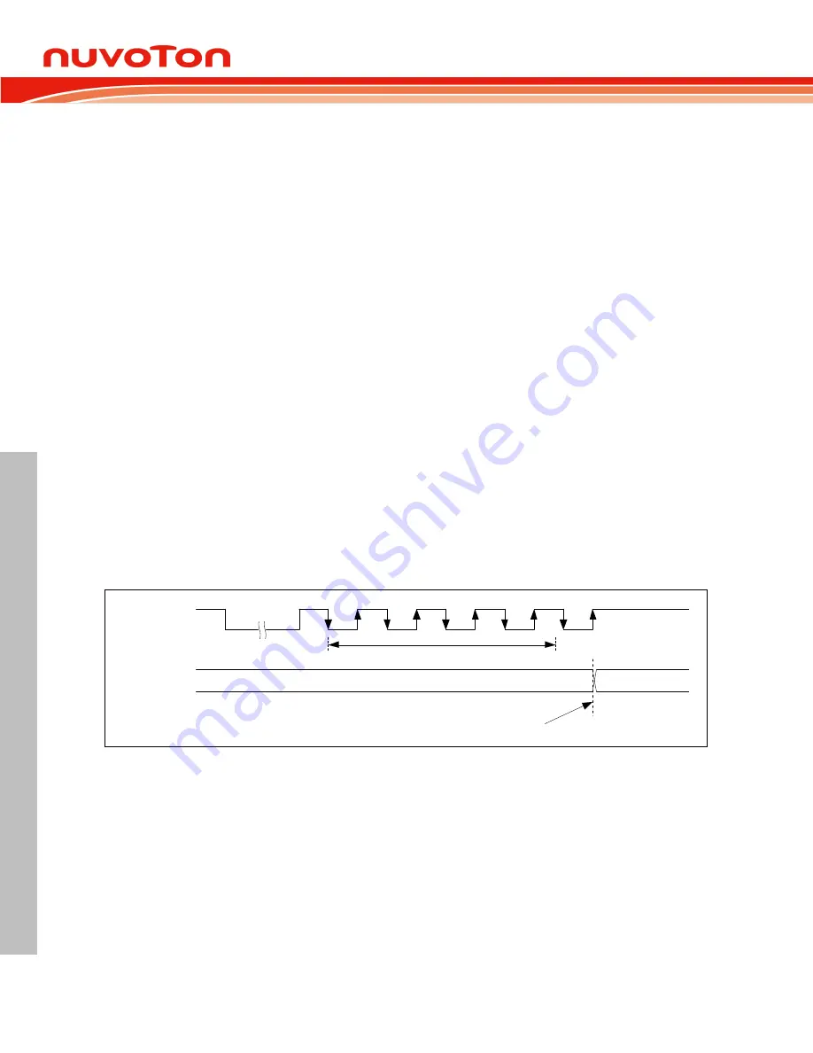
When the automatic resynchronization function is enabled, after each LIN break field, the time duration
between five falling edges is sampled on peripheral clock and the result of this measurement is stored
in an internal 13-bit register and the UART_BAUD register value will be automatically updated at the
end of the fifth falling edge. If the measure timer (13-bit) overflows before five falling edges, then the
header error flag SLVHEF (UART_LINSTS [1]) will be set.
start
bit0
bit1
bit2
bit3
bit4
bit5
bit6
bit7
stop
UART_BAUD
(m)
UART_BAUD
(n)
Measurement time
Break field
LIN Bus
UART_BAUD
Update baud rate if auto re-sync
function enable
Figure 6.23-21 LIN Sync Field Measurement
When operating in Automatic Resynchronization (AR) mode, software must select the desired baud
rate by setting the UART_BAUD register and hardware will store it at internal TEMP_REG register,
after each LIN break field, the time duration between five falling edges is sampled on peripheral clock
and the result of this measurement is stored in an internal 13-bit register BAUD_LIN and the result will
be updated to UART_BAUD register automatically.
To guarantee the transmission baud rate, the baud rate generator must reload the initial value before
each new break reception. The initial value is programmed by the application during initialization
(TEMP_REG). User can set SLVDUEN (UART_LINCTL [3]) to enable auto reload initial baud rate
value function. If the SLVDUEN (UART_LINCTL [3]) is set, when received the next character,
hardware will auto reload the initial value to UART_BAUD, and when the UART_BAUD be updated,
the SLVDUEN (UART_LINCTL [3]) will be cleared automatically. The behavior of LIN updated method
as shown in Figure 6.23-22.


