INSTALLING AND REMOVING THE OPTIONAL UNIT
5-3
4
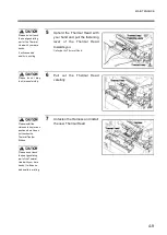
Insert the interface board along
the rail and fasten it with the
accessory bolt and the
unfastened bolt in step 3.
5
Set up interface communication.
For details of how to set up the interface,
please read “3.5 Operations under Interface
Mode” on page 3-65.
<Removing Procedures>
Please complete the operation by following
the reversed order of installation procedures
starting from step 4.
Please be sure that
the interface board is
inserted.
If the insertion is loose
the printer might not
be able to recognize
the interface.
Summary of Contents for DURA SI600
Page 1: ...THERMAL PRINTER INSTRUCTION MANUAL ...
Page 2: ......
Page 19: ...BEFORE OPERATION 1 3 Rear View ...
Page 20: ...BEFORE OPERATION 1 4 Operating Panel ...
Page 36: ...BEFORE OPERATION 1 20 ...
Page 48: ...BASIC OPERATIONS 2 12 ...
Page 54: ...SETUP PROCEDURE 3 6 3 1 3 Menu Flow of Setting Mode ...
Page 166: ...INSTALLING AND REMOVING THE OPTIONAL UNIT 5 12 ...
Page 167: ...INSTALLING AND REMOVING THE OPTIONAL UNIT 5 13 ...
Page 174: ......
Page 175: ...P N A2302B SECOND VERSION ...

