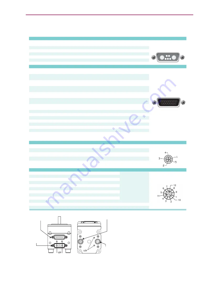
Class 5 D-Style Connector Pinouts
Class 5 D-Style Connector Pinouts
The following table shows the pinouts for the connectors on the Class 5 D-style SmartMotors.
PIN
MAIN POWER
P1
1
I/O – 6 GP, Index Input or “G” Command
25 mAmp Sink or Source
10 Bit 0-5 VDC A/D
Redundant connection on
I/O connector
7W2 Combo
D-Sub Connector
2
+5 VDC Out
50 mAmps Max (total)
3
RS-232 Transmit
Com ch. 0
115.2 KBaud Max
4
RS-232 Receive
Com ch. 0
115.2 KBaud Max
5
Common Ground (typ. SIG Ground)
A1
Main Power: +20-48VDC
A2
Common Ground (req’d. POWER Ground)
PIN
I/O CONNECTOR (5V TTL I/O)
P2
1
I/O – 0 GP or Encoder A or Step Input
25 mAmp Sink or Source
10 Bit 0-5 VDC A/D
1.5 MHz Max as Encoder
or Step Input
P2 DB-15 D-Sub Connector
2
I/O – 1 GP or Encoder B or Direction Input
25 mAmp Sink or Source
10 Bit 0-5 VDC A/D
1.5 MHz Max as Encoder
or Direction Input
3
I/O – 2 Positive Over Travel or GP
25 mAmp Sink or Source
10 Bit 0-5 VDC A/D
4
I/O – 3 Negative Over Travel or GP
25 mAmp Sink or Source
10 Bit 0-5 VDC A/D
5
I/O – 4 GP, IIC (SDA) or
RS-485 A (Com ch. 1)
25 mAmp Sink or Source
10 Bit 0-5 VDC A/D
115.2 KBaud Max
6
I/O – 5 GP, IIC (SCL) or
RS-485 B (Com ch.1)
25 mAmp Sink or Source
10 Bit 0-5 VDC A/D
115.2 KBaud Max
7
I/O – 6 GP, Index Input or “G” Command
25 mAmp Sink or Source
10 Bit 0-5 VDC A/D
Redundant connection on
Main Power Connector
8
Phase A Encoder Output
9
Phase B Encoder Output
10
RS-232 Transmit; For -CDS/7, CAN-L only Com ch. 0
115.2 KBaud Max
11
RS-232 Receive; For -CDS/7, CAN-H only
Com ch. 0
115.2 KBaud Max
12
+5 VDC Out
50 mAmp Max (total)
13
Common Ground (typ. SIG Ground)
14
Common Ground
15
Main Power: +20-48 VDC
If DE Option, Control Power
separate from Main Power
PIN
CAN bus
Connection:
P3
1
NC
NC
2
+V
NC except DeviceNet
3
-V (ground, not common)
4
CAN-H
1 MBaud Max
5
CAN-L
1 MBaud Max
PIN
Isolated 24 VDC I/O Connector
Max Load (sourcing)
P4
1
I/O – 16 GP
150 mAmps
M12 12-Pin
Female End View
2
I/O – 17 GP
150 mAmps
3
I/O – 18 GP
150 mAmps
4
I/O – 19 GP
150 mAmps
5
I/O – 20 GP
300 mAmps
6
I/O – 21 GP
300 mAmps
7
I/O – 22 GP
300 mAmps
8
I/O – 23 GP
300 mAmps
9
I/O – 24 GP
300 mAmps
10
I/O – 25 GP
300 mAmps
11
+24 Volts Input
18-32 VDC
12
Ground-I/O (not common)
P3 5-Pin CAN
(female is standard)
P4 12-Pin Expanded I/O Connector
P1 7-Pin Combo
D-Sub Power
& I/O
P2 15-Pin D-Sub I/O
M12 5-Pin
15 14 13 12 11 10 9
8 7 6 5 4 3 2 1
11 10
9
A1
A2
1 2
3 4 5
Female
Notes:
Input current < 10 mA
CAN Ground
Isolated
Notes:
Notes:
NOTE:
All specifications are subject to change without notice. Consult the factory for the latest information.
Notes:
NOTE:
I/O ports input impedance = 5 kohm (5 kohm pull-up resistor)
These I/O ports also
support analog input
CAUTION: Pins 14 and 15 are intended for use with
DE series motors for control power only. Attempt-
ing to power a non-DE motor through those pins, as
main servo-drive power, may result in immediate
damage to the electronics, which will void the war-
ranty.
CAUTION: Connectors P3 and P4
must be finger
tightened only! DO NOT use a tool. Doing so can cause
overtightening of the connection, which may damage
the connector and will void the warranty.
Isolated
Must be Main Power Ground
Specifications:
Specifications:
+5 VDC Out; For -CDS7, CAN-H only
I/O – 6 GP, Index Input or “G” Command;
For -CDS7, CAN-L only
Moog Animatics Class 5 SmartMotor™
Installation and Startup Guide,
Rev. I
Page 67 of 76


