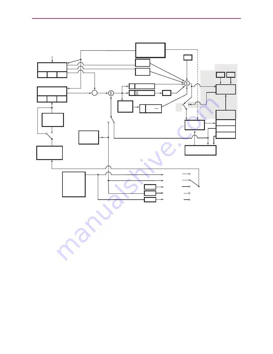
SmartMotor Theory of Operation
The following block diagram illustrates the relationship between the functional areas in the
SmartMotor.
Trajectory 1
MP
MV
MD
Trajectory 2
MC
MFR
MSR
P
e KP
I
KI edt
Cam
function
1,2
VT= AT= DT=
PT= PRT= ADT=
E
NC
1
E
NC
0
External
Encoder
+
G, X, OFF, S
MTB
PWM
Commutation
Motor
Encoder
KV
KA
Vel
Control
on/off
RPC
RPA
+
e
–
Accel
D
KD
KS
KL
KG
+
+
+
+ +
+
Hall sensor
de
dt
SRC(2)
SRC(1)
SRC(0)
SRC(-1)
SRC(-2)
filter
*
*
*
*
*
Internal
Clock:
1 tick per
PID cycle
-1
*
Null
-1
*
RC
TR(1
)
RCTR(0)
1. MFMUL and MFDIV commands do not have an effect on dwell time or distance. Dwell is strictly based on raw master encoder counts selected by the
SRC( ) command specifying internal virtual or external master count source.
2. When feeding a Cam table with a gearing profile, changes to MFMUL and MFDIV will affect the time it takes to move through a Cam table but will
not
affect dwell time, as specified in the previous note.
NOTES:
Current
sensors
Current
control
KII KPI
Torque
command
MDC
MDS
MDE
MDT
Not supported on
D-style motors
MFA
MFD
MFSLEW
MFSDC
1
Trapezoidal
Move Profile
INTERMEDIATE
COUNTS
SOURCE
COUNTS
SmartMotor Theory of Operation Diagram
Moog Animatics Class 5 SmartMotor™
Installation and Startup Guide,
Rev. I
Page 24 of 76


