
MDS-E/EH Series Instruction Manual
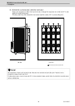
1 Installation
37
IB-1501229-F
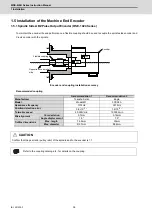
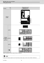
1.5.2 Spindle Side PLG Serial Output Encoder (TS5690, MU1606 Series)
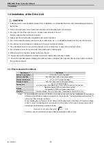
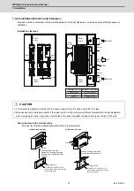
(1) Part configuration
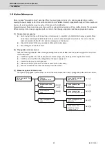
The encoder is configured of a sensor and detection gear. The sensor and detection gear must be used in the
designated combination.
These are precision parts, and require care when handling. Do not apply an excessive force on the sensor's
detection surface, as this could result in faults. Do not pull and apply a load on the lead wires. Make sure that
foreign matters (iron chips, etc.) do not get on the sensor's detection surface or detection gears. If any foreign
matter should get on these parts, carefully remove while taking care not to damage the parts. When handling the
detection gears, take care not to damage or deform the teeth.
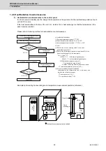
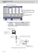
Spindle side PLG serial output encoder TS5690 Series
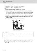
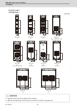
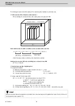
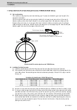
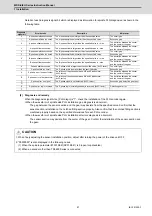
(2) Installing the detection gears
[1] Install the detection gears so that the first gear's teeth side (Z phase) face the sensor's lead side.
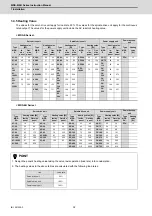
[2] The detection gears and shaft or sleeve should be fixed with shrink fitting. Refer to the following table for the
shrink fitting values. The detection gears should be heated evenly between 120 and 150°C using an electric
furnace, etc.
Guideline for detection gear shrink fitting values
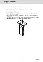
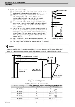
[3] Keep the run-out of the outer diameter, when the detection gears are installed on the shaft, to 0.02mm or less.
[4] To remove a detection gear fixed with shrink fitting, use the screw holes opened in the axial direction for pulling
(two M5 screw holes or two M8 screw holes), or push the end with a jig. Carry out this work carefully. Applying
excessive force when pulling out the gears could cause the inner diameter of the detection gears to deform.
[5] Before reusing detection gears which have been removed, always measure the inner diameter dimensions,
and carefully check that the inner diameter is not deformed, and that the sufficient tightening amount can be
secured. Do not reuse the detection gears if the inner diameter is deformed, or if any abnormality such as
damage to the teeth is found.
Inner diameter (mm)
Shrink fitting (mm)
Inner diameter (mm)
Shrink fitting (mm)
Φ
40
0.020 to 0.040
Φ
140
0.050 to 0.085
Φ
70
0.030 to 0.055
Φ
160
0.060 to 0.090
Φ
80
0.030 to 0.055
Φ
215
0.080 to 0.110
Φ
125
0.050 to 0.085
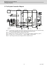
Detection
gears
Sensor section
*
Thermal sensor terminals are not used
when the encoder is installed on the spindle side.
Output
connector
* Thermal sensor terminals
Summary of Contents for MDS-E
Page 1: ......
Page 3: ......
Page 15: ......
Page 17: ......
Page 19: ......
Page 21: ......
Page 31: ......
Page 32: ...1 IB 1501229 F 1 Installation ...
Page 76: ...45 IB 1501229 F 2 Wiring and Connection ...
Page 132: ...101 IB 1501229 F 3 Safety Function ...
Page 142: ...111 IB 1501229 F 4 Setup ...
Page 277: ...MDS E EH Series Instruction Manual 4 Setup 246 IB 1501229 F ...
Page 278: ...247 IB 1501229 F 5 Servo Adjustment ...
Page 351: ...MDS E EH Series Instruction Manual 5 Servo Adjustment 320 IB 1501229 F ...
Page 352: ...321 IB 1501229 F 6 Spindle Adjustment ...
Page 404: ...373 IB 1501229 F 7 Troubleshooting ...
Page 455: ...MDS E EH Series Instruction Manual 7 Troubleshooting 424 IB 1501229 F ...
Page 456: ...425 IB 1501229 F 8 Maintenance ...
Page 475: ...MDS E EH Series Instruction Manual 8 Maintenance 444 IB 1501229 F ...
Page 476: ...445 IB 1501229 F 9 Power Backup System ...
Page 494: ...463 IB 1501229 F 10 Appx 1 Cable and Connector Assembly ...
Page 504: ...473 IB 1501229 F 11 Appx 2 D A Output Specifications for Drive Unit ...
Page 514: ...483 IB 1501229 F 12 Appx 3 Protection Function ...
Page 523: ...MDS E EH Series Instruction Manual 12 Appx 3 Protection Function 492 IB 1501229 F ...
Page 524: ...493 IB 1501229 F 13 Appx 4 Compliance to EC Directives ...
Page 528: ...497 IB 1501229 F 14 Appx 5 EMC Installation Guidelines ...
Page 540: ...509 IB 1501229 F 15 Appx 6 Higher Harmonic Suppression Measure Guidelines ...
Page 550: ......
Page 554: ......


