
MDS-E/EH Series Instruction Manual
6 Spindle Adjustment
341
IB-1501229-F
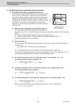
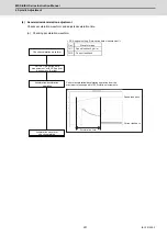
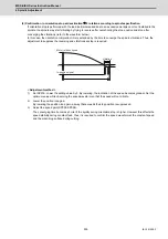
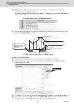
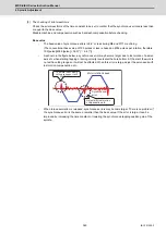
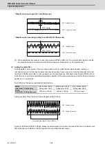
6.1.6 High-speed Synchronous Tapping
This function uses high-speed communication between drive units to send compensation data from a spindle to a servo
system. The servo system uses the received data for compensation to follow the spindle position, and reduce
synchronous errors. This function can also suppress speed overshoot in cases of acceleration/deceleration at time
constants that may reach the spindle torque limit. As such, shorter time constants can be set compared to the
conventional normal synchronous tapping, and cycle times can be reduced. However, high-speed synchronous tapping
function does not guarantee higher machining accuracy than normal synchronous tapping.
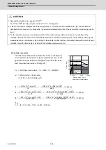
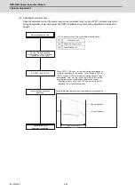
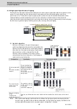
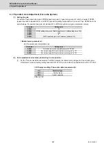
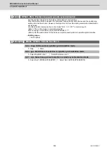
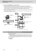
(1) System Configuration
As shown in the figure on the right, the high-speed
synchronous tapping function uses the communication line
between the drive units and NC for compensating between
drive units. Also, the output and receiving of compensation
data of each drive unit is commanded from the NC.
Therefore, there are limitations in how drive units are
connected and the order of connection. The following are
cautions when using this function.
(Note)
When synchronous tapping is performed under conditions that high-speed synchronous tapping function
cannot be used, operation continues without compensation. During synchronous tapping, the status can be
confirmed with bit8 in spindle control command output 6. (0: Disabled, 1: Enabled)
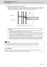
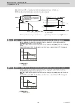
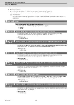
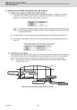
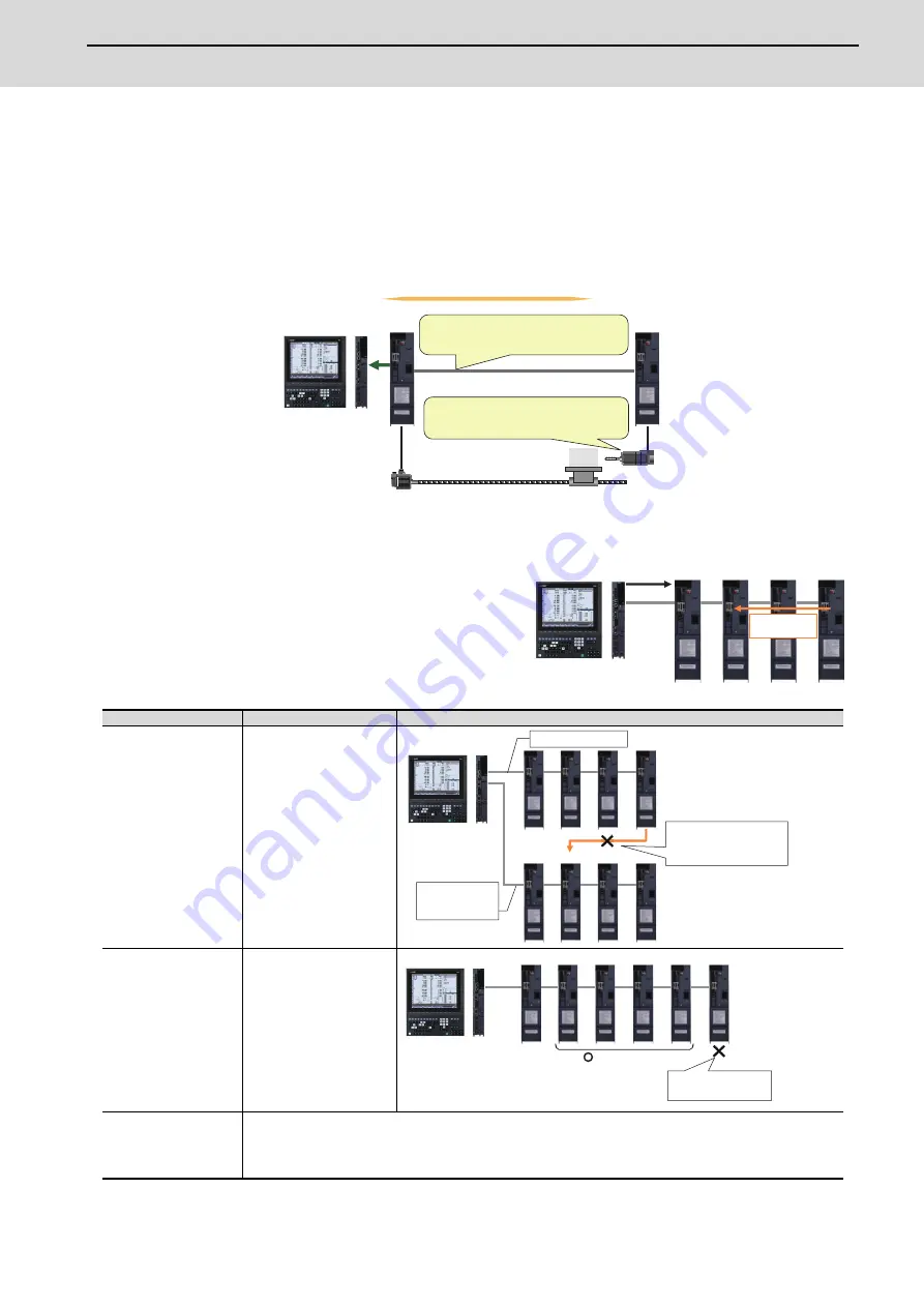
Configuration
Specification
Connection examples
Optical communication
line
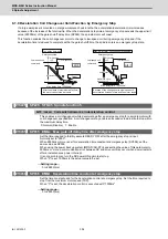
Connection of multiple
channels
Drive units that perform
high-speed synchronous
tapping are restricted to
axes connected with the
same optical
communication line in the
same channel.
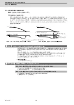
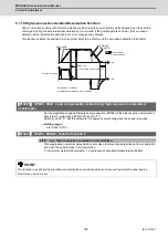
The connection order
of drive units in the
same channel
The maximum number of
spindles that can be used
in high-speed
synchronous tapping is 4.
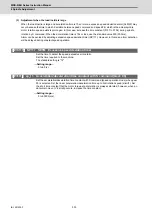
Synchronous tapping
in G68
(
3-dimensional
coordinate conversion
)
When any one of three base axes cannot satisfy the above specifications, this function cannot be used in
G68.
MDS-E
MDS-E
M800/M80/C80
Servo
Spindle
Series
High-speed Synchronous Tapping Function
(
OMR-DD
)
(1) High-speed communication between drive units
suppresses synchronous errors between a servo
drive unit and a spindle drive unit.
(2) Speed overshoot is suppressed when
stopping or at a hole bottom while accelerating
/decelerating at spindle maximum torque
Compensation
data
Spindle
Servo
Compensation data
sending/receiving
command
Spindle
Servo
Optical communication
channel 1
Optical
communication
channel 2
Compensation over different
optical communication
channels cannot be
performed
Spindle 3
Servo Spindle 1
Spindle 4
Spindle 2
High-speed synchronous
tapping function cannot
be used.
Up to a maximum
of 4 spindles
Spindle 5
Summary of Contents for MDS-E
Page 1: ......
Page 3: ......
Page 15: ......
Page 17: ......
Page 19: ......
Page 21: ......
Page 31: ......
Page 32: ...1 IB 1501229 F 1 Installation ...
Page 76: ...45 IB 1501229 F 2 Wiring and Connection ...
Page 132: ...101 IB 1501229 F 3 Safety Function ...
Page 142: ...111 IB 1501229 F 4 Setup ...
Page 277: ...MDS E EH Series Instruction Manual 4 Setup 246 IB 1501229 F ...
Page 278: ...247 IB 1501229 F 5 Servo Adjustment ...
Page 351: ...MDS E EH Series Instruction Manual 5 Servo Adjustment 320 IB 1501229 F ...
Page 352: ...321 IB 1501229 F 6 Spindle Adjustment ...
Page 404: ...373 IB 1501229 F 7 Troubleshooting ...
Page 455: ...MDS E EH Series Instruction Manual 7 Troubleshooting 424 IB 1501229 F ...
Page 456: ...425 IB 1501229 F 8 Maintenance ...
Page 475: ...MDS E EH Series Instruction Manual 8 Maintenance 444 IB 1501229 F ...
Page 476: ...445 IB 1501229 F 9 Power Backup System ...
Page 494: ...463 IB 1501229 F 10 Appx 1 Cable and Connector Assembly ...
Page 504: ...473 IB 1501229 F 11 Appx 2 D A Output Specifications for Drive Unit ...
Page 514: ...483 IB 1501229 F 12 Appx 3 Protection Function ...
Page 523: ...MDS E EH Series Instruction Manual 12 Appx 3 Protection Function 492 IB 1501229 F ...
Page 524: ...493 IB 1501229 F 13 Appx 4 Compliance to EC Directives ...
Page 528: ...497 IB 1501229 F 14 Appx 5 EMC Installation Guidelines ...
Page 540: ...509 IB 1501229 F 15 Appx 6 Higher Harmonic Suppression Measure Guidelines ...
Page 550: ......
Page 554: ......


