


MDS-E/EH Series Instruction Manual
8 Maintenance
438
IB-1501229-F
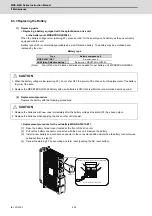
8.2 Service Parts
A guide to the part replacement cycle is shown below. Note that these will differ according to the working conditions or
environmental conditions, so replace the parts if any abnormality is found. Contact Mitsubishi branch or your dealer for
repairs or part replacements.
[1] Power smoothing capacitor:
The characteristics of the power smoothing capacitor will deteriorate due to the effect of ripple currents, etc. The
capacitor life is greatly affected by the ambient temperature and working conditions. However, when used
continuously in a normal air-conditioned environment (ambient temperature is an average of 40°C or less), the
service life will be ten years.
[2] Relays:
Contact faults will occur due to contact wear caused by the switching current. The service life will be reached after
100,000 cumulative switches (switching life) although this will differ according to the power capacity.
[3] Servo motor bearings:
The motor bearings should be replaced after 20,000 to 30,000 hours of rated load operation at the rated speed.
This will be affected by the operation state, but the bearings must be replaced when any abnormal noise or vibration
is found in the inspections.
[4] Servo motor oil seal, V-ring:
These parts should be replaced after 5,000 hours of operation at the rated speed. This will be affected by the
operation state, but these parts must be replaced if oil leaks, etc., are found in the inspections.
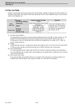
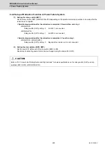
Part name
Standard replacement time
Remarks
Servo
drive unit
Smoothing capacitor
10 years
The standard replacement time is
a reference. Even if the standard
replacement time is not reached,
the part must be replaced if any
abnormality is found.
Cooling fan
10,000 to 30,000 hours (2 to 3 years)
Battery
10,000 hours
(for MDS-BAT6V1SET,
MDSBTBOX-LR2060)
Servo motor
Bearings
20,000 to 30,000 hours
Encoder
20,000 to 30,000 hours
Oil seal, V-ring
5,000 hours
Summary of Contents for MDS-E
Page 1: ......
Page 3: ......
Page 15: ......
Page 17: ......
Page 19: ......
Page 21: ......
Page 31: ......
Page 32: ...1 IB 1501229 F 1 Installation ...
Page 76: ...45 IB 1501229 F 2 Wiring and Connection ...
Page 132: ...101 IB 1501229 F 3 Safety Function ...
Page 142: ...111 IB 1501229 F 4 Setup ...
Page 277: ...MDS E EH Series Instruction Manual 4 Setup 246 IB 1501229 F ...
Page 278: ...247 IB 1501229 F 5 Servo Adjustment ...
Page 351: ...MDS E EH Series Instruction Manual 5 Servo Adjustment 320 IB 1501229 F ...
Page 352: ...321 IB 1501229 F 6 Spindle Adjustment ...
Page 404: ...373 IB 1501229 F 7 Troubleshooting ...
Page 455: ...MDS E EH Series Instruction Manual 7 Troubleshooting 424 IB 1501229 F ...
Page 456: ...425 IB 1501229 F 8 Maintenance ...
Page 475: ...MDS E EH Series Instruction Manual 8 Maintenance 444 IB 1501229 F ...
Page 476: ...445 IB 1501229 F 9 Power Backup System ...
Page 494: ...463 IB 1501229 F 10 Appx 1 Cable and Connector Assembly ...
Page 504: ...473 IB 1501229 F 11 Appx 2 D A Output Specifications for Drive Unit ...
Page 514: ...483 IB 1501229 F 12 Appx 3 Protection Function ...
Page 523: ...MDS E EH Series Instruction Manual 12 Appx 3 Protection Function 492 IB 1501229 F ...
Page 524: ...493 IB 1501229 F 13 Appx 4 Compliance to EC Directives ...
Page 528: ...497 IB 1501229 F 14 Appx 5 EMC Installation Guidelines ...
Page 540: ...509 IB 1501229 F 15 Appx 6 Higher Harmonic Suppression Measure Guidelines ...
Page 550: ......
Page 554: ......


