


MDS-E/EH Series Instruction Manual
10 Appx. 1: Cable and Connector Assembly
467
IB-1501229-F
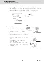
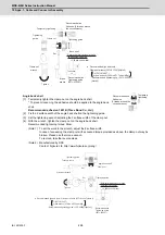
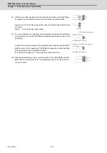
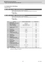
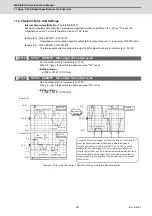
Angle back shell
[1] Fix the 2 surface width of the angle back shell on the tightening guide.
[2] Set the back shell wrench adjusting to the 2 surface width of the back shell coupling.
[3] With the wrench, tighten the back shell coupling to the angle back shell.
Recommended tightening torque: 4 to 5N.m
(Note 1) When setting the work to the wrench, adjust it to the 2 surface width.
To remove, take the reverse steps.
(Note 2) To change the back shell angle, adjust the toothing position of the plug shell and back shell.
(Note 3) Manufactured by DDK
Contact: Fujikura Ltd. http://www.fujikura.co.jp/eng/
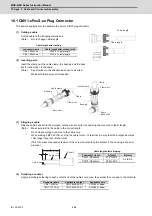
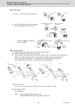
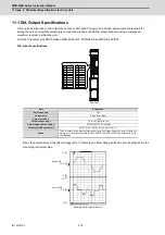
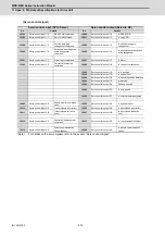
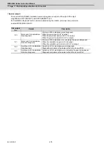
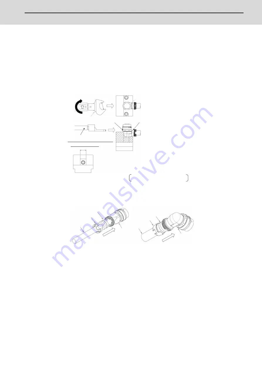
(8) Insert a busing and a cable clamp
Insert the bushing and the cable clamp in the back shell.
(Note)
After the Bushing insert, confirm that cable position should be inside of Bushing.
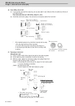
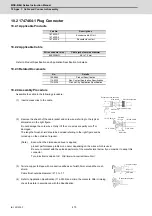
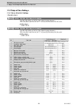
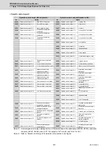
(9) Tightening a clamp nut
Straight back shell
[1] Temporarily tighten the clamp nut on the straight back shell.
*To prevent the loosening, it is recommended to coat the straight back shell with adhesive.
Recommended adhesive: 1401B (Three Bond Co., Ltd.)
[2] Fix the 2 surface width of the straight back shell on the tightening guide.
[3] With the wrench, tighten the clamp nut on the straight back shell.
Recommended tightening torque: 4 to 5N•m
(Note 1) When setting the work to the wrench, adjust the 2 surface width.
To remove, take the reverse steps.
(Note 2) Manufactured by DDK
Contact: Fujikura Ltd. http://www.fujikura.co.jp/eng/
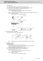
15
19
Torque wrench
Tighten
(Back shell width)
Angle back shell
Tightening guide
* Referential dimensions for back
shell tightening guide
● Recommended jigs and tools : Back shell wrench (357J-51333T)
Bit (357J-51344T)
Torque wrench (CL6N x 8D,Tonichi Mfg.)
Back shell
coupling
Set
Set
* Recommendation:
Tightening guide
(357J-52658T)
Angle back shell
wrench
* Recommended tightening guide: (357J-53402T) (Note 3)
(Note 3)
Cable clamp
Cable
Bushing
Back shell
Insert
Cable
Cable clamp
Bushing
Back shell
Insert
Summary of Contents for MDS-E
Page 1: ......
Page 3: ......
Page 15: ......
Page 17: ......
Page 19: ......
Page 21: ......
Page 31: ......
Page 32: ...1 IB 1501229 F 1 Installation ...
Page 76: ...45 IB 1501229 F 2 Wiring and Connection ...
Page 132: ...101 IB 1501229 F 3 Safety Function ...
Page 142: ...111 IB 1501229 F 4 Setup ...
Page 277: ...MDS E EH Series Instruction Manual 4 Setup 246 IB 1501229 F ...
Page 278: ...247 IB 1501229 F 5 Servo Adjustment ...
Page 351: ...MDS E EH Series Instruction Manual 5 Servo Adjustment 320 IB 1501229 F ...
Page 352: ...321 IB 1501229 F 6 Spindle Adjustment ...
Page 404: ...373 IB 1501229 F 7 Troubleshooting ...
Page 455: ...MDS E EH Series Instruction Manual 7 Troubleshooting 424 IB 1501229 F ...
Page 456: ...425 IB 1501229 F 8 Maintenance ...
Page 475: ...MDS E EH Series Instruction Manual 8 Maintenance 444 IB 1501229 F ...
Page 476: ...445 IB 1501229 F 9 Power Backup System ...
Page 494: ...463 IB 1501229 F 10 Appx 1 Cable and Connector Assembly ...
Page 504: ...473 IB 1501229 F 11 Appx 2 D A Output Specifications for Drive Unit ...
Page 514: ...483 IB 1501229 F 12 Appx 3 Protection Function ...
Page 523: ...MDS E EH Series Instruction Manual 12 Appx 3 Protection Function 492 IB 1501229 F ...
Page 524: ...493 IB 1501229 F 13 Appx 4 Compliance to EC Directives ...
Page 528: ...497 IB 1501229 F 14 Appx 5 EMC Installation Guidelines ...
Page 540: ...509 IB 1501229 F 15 Appx 6 Higher Harmonic Suppression Measure Guidelines ...
Page 550: ......
Page 554: ......


