

MDS-E/EH Series Instruction Manual
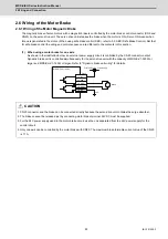
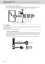
2 Wiring and Connection
93
IB-1501229-F
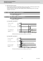
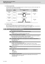
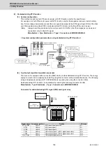
2.7.3 Spindle Coil Changeover
There are spindle motors capable of coil changeover control, which enables favorable characteristics to be attained from
low speeds to high speeds by changing two types of coils.
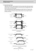
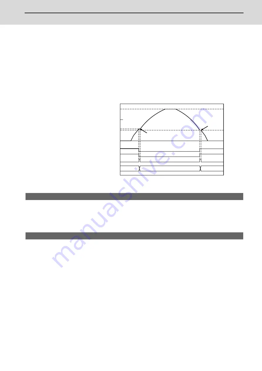
(1) Coil changeover control
The speed at which to change the coils is detected by the spindle drive according to the value set with spindle
parameter SP028. This is conveyed to the NC with a speed detection (SD) signal. The NC judges the other
conditions (coil fixed, etc.), and issue a coil changeover command to the spindle drive with the L coil selection
command (LCS).
To prevent the contactor from varying, the hysteresis set with SP029 is applied on the speed when changing from
the low-speed coil to the high-speed coil and the high-speed coil to the low-speed coil.
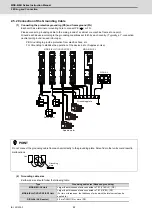
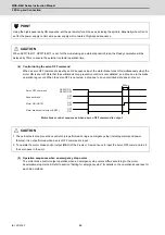
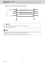
Spindle motor coil changeover control
【
#13028
】
SP028 SDTS Speed detection set value
Set the motor speed for detecting the speed.
If the motor speed drops below the set speed, the speed detection signal turns ON.
The standard setting is 10% of the maximum motor speed.
---Setting range---
10 to 32767 (r/min)
【
#13029
】
SP029 SDTR Speed detection reset width
Set the hysteresis width in which the speed detection changes from ON to OFF.
If the setting value is small, the speed detection will chatter easily.
The standard setting is "30".
---Setting range---
10 to 1000 (r/min)
Spindle motor speed
(r/min)
Speed detection (SD1)
L coil selection command (LCS)
Changing coil (MKC)
Contactor changeover
speed coil
Low-
Time
High-speed coil
Low-speed coil
[SP
→
NC]
[NC
SP]
[SP
NC]
0
2000
6000
4000
(SP028+SP029)
SP028
→
→
Summary of Contents for MDS-E
Page 1: ......
Page 3: ......
Page 15: ......
Page 17: ......
Page 19: ......
Page 21: ......
Page 31: ......
Page 32: ...1 IB 1501229 F 1 Installation ...
Page 76: ...45 IB 1501229 F 2 Wiring and Connection ...
Page 132: ...101 IB 1501229 F 3 Safety Function ...
Page 142: ...111 IB 1501229 F 4 Setup ...
Page 277: ...MDS E EH Series Instruction Manual 4 Setup 246 IB 1501229 F ...
Page 278: ...247 IB 1501229 F 5 Servo Adjustment ...
Page 351: ...MDS E EH Series Instruction Manual 5 Servo Adjustment 320 IB 1501229 F ...
Page 352: ...321 IB 1501229 F 6 Spindle Adjustment ...
Page 404: ...373 IB 1501229 F 7 Troubleshooting ...
Page 455: ...MDS E EH Series Instruction Manual 7 Troubleshooting 424 IB 1501229 F ...
Page 456: ...425 IB 1501229 F 8 Maintenance ...
Page 475: ...MDS E EH Series Instruction Manual 8 Maintenance 444 IB 1501229 F ...
Page 476: ...445 IB 1501229 F 9 Power Backup System ...
Page 494: ...463 IB 1501229 F 10 Appx 1 Cable and Connector Assembly ...
Page 504: ...473 IB 1501229 F 11 Appx 2 D A Output Specifications for Drive Unit ...
Page 514: ...483 IB 1501229 F 12 Appx 3 Protection Function ...
Page 523: ...MDS E EH Series Instruction Manual 12 Appx 3 Protection Function 492 IB 1501229 F ...
Page 524: ...493 IB 1501229 F 13 Appx 4 Compliance to EC Directives ...
Page 528: ...497 IB 1501229 F 14 Appx 5 EMC Installation Guidelines ...
Page 540: ...509 IB 1501229 F 15 Appx 6 Higher Harmonic Suppression Measure Guidelines ...
Page 550: ......
Page 554: ......


